background image

Chapter 5: Fault Check

Installation and Maintenance Manual

20

5.1: PLS Output Status on Fault Conditions

1)

If a fault condition is detected, 

ALL

 limit switch outputs will turn off and the display will

show the following:

EE0

=

Resolver Not Plugged in or Resolver Primary Open

EE1

=

Resolver Secondary S1-S3 Open or Shorted

EE2

=

Resolver Secondary S2-S4 Open or Shorted

EE3

=

Resolver Shorted - Primary Winding or Resolver Excitation Fault

EE4

=

Electronic Transducer Tracking Fault

No Message Microprocessor or 5 Volt Power Supply Failure

The message will remain on the display and the outputs will be off until the problem is

corrected and the fault reset button is pressed and released to reactivate the fault output

and return the display and outputs to their normal operation.

2)

If the fault condition is the result of a microprocessor failure or lockup, the state of the

limit switch output circuits cannot be predicted.  However, the fault check output will

turn off until the fault is cleared and the fault reset button is pressed and released.

Removal and reapplication of power to the PLS system may clear a locked-up

condition.

www.comoso.com

Summary of Contents for Gemco 1995A Series

Page 1: ...Micro Set Programmable Limit Switch Gemco Series 1995A Installation Programming Manual www comoso com ...

Page 2: ...checked the accuracy of this manual at the time it was printed Any comments you may have for the improvement of this manual are welcomed AMETEK reserves the right to revise and redistribute the entire contents or selected pages of this manual All rights to the contents of this manual are reserved by AMETEK Preface This manual is for the Installation and Maintenance of the Gemco Series 1995A Micro ...

Page 3: ...m AvailableOnlyon P OptionUnits 6 3 7 Setpoint Formula 7 3 8 Setpoints 8 3 9 Clear an Existing Setpoint 10 3 10 Clear All Setpoints 10 3 11SetpointAvailability 10 3 12ElectronicOffset 11 3 13 Reset to Preset 11 3 14 Motion Detector 12 3 15 Power Up in a Position or RPM 13 3 16DecimalPointProgramming 13 3 17Enable DisableOutputs 14 3 18 Linear Speed Offset Available Only on Option P Units 14 3 19 P...

Page 4: ...Power Quality Consideration 24 8 4 Grounding 24 8 5 Incoming Power 24 8 6 Low Level Inputs 24 Chapter 9 Specifications 26 9 1 1995 Micro Set PLS Programmer 26 9 2 Mechanical Relay Single Pole Double Throw 26 9 3 AC Solid State Single Pole Normally Open 26 9 4 DC Solid State Single Pole Normally Open 27 9 5 1995E Output Expansion Module 27 9 6 1995 1446 Remote Circular Display 27 Chapter 10 Trouble...

Page 5: ... microcomputer basedProgrammableLimitSwitch PLS with a convenient keypad for programming each independent output circuit to open or close at thedesiredsettings Thissystemallowsprecisepositioncontrolofrotarymotion A1995Aconsists of a resolver based transducer resolver to programmer cable assembly and the programmer whichprovidessixlimitswitchoutputsandonefaultcheckoutput Theoptionaloutput expansion...

Page 6: ...eed increases or decreases This option automatically adjusts specified circuits based on speed n Time Based Outputs Specified outputs can be programmed to turn on based on position and turn off based on time 0 01 9 99 seconds 1 3 Controller Features and Functions The controller is housed in an all metal case that can be panel mounted The controller consists of a keypad a CPU Board and a Power Supp...

Page 7: ...ting holes and sizes for each component are shown on Pages 6 and 7 of the 1995A catalogsection The controller should be mounted in the appropriate panel cutout and securely bolted into place using thefour 4 3 16 diametermountingholes NOTE In instances where the 1995A is being mounted directly on a mechanical stamping press care should be taken to isolate the controller from shock load and vibratio...

Page 8: ...his system is shown in Fig 11 3 Chapter 11 Wiring Diagrams This wiring diagram is applicable for all standard 1995 PLS s 2 3 Wiring Instructions Attach the pre wired plug on the resolver transducer cable to the transducer and route the shielded cable through a separate grounded earth ground metal conduit to the panel Connect the mating half terminal block to the 1995A PLS Be sure the shield wire i...

Page 9: ...2 Initialization The following key commands should be entered on the keypad to clear all programmed data upon installation and PRIOR to programming This sequence clearsallprogrammeddata Alloperatingparametersmustbereprogrammedafterusingthisinitializa tionfunction 3 3 Scale Factor NOTE Programmingofthedesiredscalefactororthenumberofoutputswilldeleteallprogrammed data held in memory Therefore these ...

Page 10: ... number of outputs is 24 NOTE Ifanumberisenteredthatisnotamultipleofsix theunitwillstorethenextmultipleofsix 3 6 Multiprogram Available Only on P Option Units The Multiprogram feature allows the storage of multiple sets of output sequences that are preprogrammed based on the various requirements of different tooling When dies or tooling are changed the new program is simply called up on the keypad...

Page 11: ...rams may need to be reduced Asetpoint is one CIR ON or CIR OFF entry Setpoint Programs 1467 2 Number of Programs x A S T U P T U O 6 S T U P T U O 2 1 S T U P T U O 8 1 S T U P T U O 4 2 S T U P T U O 0 3 3 5 2 1 2 4 2 1 7 0 2 1 1 8 1 1 1 6 1 1 2 1 0 2 5 2 9 9 3 5 3 4 4 9 7 2 9 6 2 8 1 2 1 4 2 8 4 3 5 2 5 3 6 6 3 2 1 7 1 8 1 0 1 4 2 7 0 3 5 1 7 9 7 7 2 4 1 3 1 0 2 8 5 2 6 ä ã Number of program Res...

Page 12: ...ts have been selected the will be the time interval that the relay will be active once the ON setpoint has been reached E Multiple ON and OFF setpoints can be programmed on each circuit All decimal points will flash when more than one setpoint exists on the selected circuit F An LS Limit Switch may not have the same value for both the ON point and the OFF point If a value is entered that is alread...

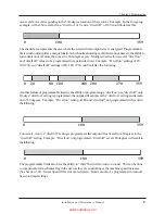
Page 13: ... off settings of 80 180 270 would look like the following Anotherfeatureofprogrammablelimitsistheabilityofprogramminga dwellon ora dwelloff only Ifonlya dwellon settingisprogrammed theoutputwillactivateatthe dwellon settingandremain on to 359 degrees Example Dwell on setting of 180 and dwell off not programmed will result in thefollowing 0 180 359 Conversely if only a dwell off setting isprogramme...

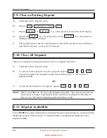
Page 14: ...complishedasfollows A Unitmustbeinthe Program mode B To clear all of the setpoints in the active program depress The active program is the program currently selected using Code 771 See Section 3 7 SetpointFormula OR C To clear all the setpoints in all programs depress CIR 9 1 ENT ENT CIR 3 9 1 NOTE CIR 91 and CIR 391 only clear out programmed setpoints They do not clear out Linear Speed ramps or c...

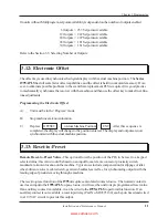
Page 15: ...epress After this sequence is completed the display will change to the position entered The display and outputs are now synchronizedwiththeactualmachineposition OFFSET ActualMachinePosition ENT 3 13 Reset to Preset Remote Reset to Preset Value This option allows the position of the PLS to be reset to a keypad selected value this value would be based on an input from a remote contact or proximity s...

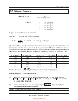
Page 16: ...ogrammed scale factor less one 1 3 14 Motion Detector A programmable Motion Detect output will energize a relay when the transducer speed exceeds the customer s preprogrammedRPMvalue Themotiondetectorissetbyenteringthefollowing A Unitmustbeinthe Program mode B The motion detect must first be enabled before you can store any values To accomplish this depress A one 1 will enable the motion ENT CIR 5...

Page 17: ...a one 1 is entered the unit will power up displayingRPM 3 16 Decimal Point Programming Acontinuous nonfloating decimal point may be programmed on the display If a scale factor is selected thatneedsadecimalpointinordertoproperlydisplayitsresolutioninengineeringunits thefollowing50 series codes are used 50 No decimal point clearsexistingdecimalpoint 123 51 Tenths 12 3 52 Hundreths 1 23 Toprogramadec...

Page 18: ...e of operation This featureisusedtocompensateforthemechanicallaginmachinecontrols The 16 step linear speed offset feature allows up to 16 different offset steps to be selected and a different amount of positive or negative advance or retard offset to be programmed between each of the sixteen steps Access Codes 501 through 516 are used to select the successive steps that define a ramp between the v...

Page 19: ...lly programmed to turn on at 150 degrees and off at 350 degrees will now be turning on at 100 degrees and off at 300 degrees while at 100 RPM The third step 503 is programmed to retard the circuits back to a total of 30 degrees as RPM continues to rise from 100 to 140 RPM The example circuit originally programmed to turn on at 150 degrees and off at 350 degrees is now turning on at 120 degrees and...

Page 20: ...and RPM point for the first offset ramp Next use Circuit 502 to program both values for the second offset ramp Continue with Circuit 503 and onward in ascending order until all desired ramps are programmed 1 CIR 501 thru 516 CIR ON Specifythetotalamountofoffset from the original output settings ENT CIR 501 thru 516 CIR OFF Specify the RPM at which the above specified amount of offset occurs ENT 2 ...

Page 21: ...on module to operate Two pairs of pins located in the lower right corner of the expansion module should be jumpered on only the last module in the wiring group However if a Remote Circular Display is being used do not install these jumpers Remove both jumpers from all intermediate expansion modules See Chapter 11 WiringDiagrams Fig 11 2foradditionalexpansionmodulewiringinformation Eachexpansionmod...

Page 22: ... set up for a position ON and a timed OFF output C This sequence only enables or disables LS1 thru LS6 for Time Based operation After an LS is enabled as a Time Basedcircuit follow normal programming instructions See Section 3 8 Setpoints C and D CIR 301 thru 306 0 or 1 ENT ENT NOTE If LS6 is set as a motion detector it cannot be set for Time Based D A Time Based output may only have one CIR ON an...

Page 23: ...may be operated by an isolated contact current sourcing or current sinking device 5V DC at 10mA Anormally closed momentary open contact button can be wired per Fig 11 3 Chapter 11 Wiring Diagrams to activate the Fault Check circuit and it will provide a method of resetting the fault output after a fault condition has been sensed To reset the Fault Check output after the fault condition has been cl...

Page 24: ...lt No Message Microprocessor or 5Volt Power Supply Failure Themessagewillremainonthedisplayandtheoutputswillbeoffuntiltheproblemis corrected and the fault reset button is pressed and released to reactivate the fault output and return the display and outputs to their normal operation 2 If the fault condition is the result of a microprocessor failure or lockup the state of the limitswitchoutputcircu...

Page 25: ...1 3 Chapter 11 Wiring Diagrams NOTE The 1995 PLS cannot be programmed until the security input has been actuated by means of connections between 5V DC and Security input and between Security input and ground NOTE If the Run Security program is not needed always in the Program mode install jumper wires form Pin 9 5V DC to Pin 10 Security and from Pin 11 Security to Pin 14 GND on the 16 place resolv...

Page 26: ...remotecirculardisplaygetsitsRS422synchronoussignalfromthefour placeterminalstriplocated on the back of the 1995 programmer The display can be located up to 1 000 feet away from the programmer See Fig 11 2 Chapter 11 Wiring Diagrams Installationandwiringoftheremotecirculardisplayshouldbefollowedinthesamemannerasthe 1995A described earlier in Chapter 2 7 1 POS RPM On Remote Circular Display The 3 4 ...

Page 27: ...tioncircuitryinthe1995programmerhasfailedand should be replaced If this voltage appears a shorted condition in the resolver or its cable should be checked The return signals from the resolver stator windings are wired to the 1995 programmer s 16 place terminal strip at terminals 4 and 5 labeled White and BK W and terminals 6 and 7 labeled Green and BK G To verity the presence of theseAC return sig...

Page 28: ... power supplies should be used to isolate microprocessor based circuitry The power on the output side of these isolation devices should be fed to the programmable limit switch and other microprocessor based devices only The loads being driven by the programmable limit switch output relays must not get their power from the output side of the isolation device Using the output side of an isolation de...

Page 29: ...ugh a remote contact or solid state switch These computer level signals must be protected frominducedelectricalnoise The contact used to activate the input should not be located outside the enclosure in which the 1995 PLS is mounted Any wiring between the 1995 PLSinput terminals and this contact located within the enclosure should be routed away from any power handling relays contactors or other n...

Page 30: ...rate to 3 arc minutes provides resolution of 1 part in 4096 2800 RPM maximum speed Logic Fault check and security 5V DC at 10mA May be operated by isolated contact current sourcing or current sinking device OUTPUTS Plug inrelayslistedbelow ContactRelay 10 Amp Isolated Contact Pick Up 2 ms Drop Out 15 ms 9 3 AC Solid State Single Pole Normally Open MaximumLoad 1 Amp LoadVoltage Range 70 250VAC Zero...

Page 31: ... 60V DC Leakage Current 2mAMaximum On StateVoltage Drop 1 5VMaximum SurgeCurrent 5A 1 Sec Maximum Min OperationalCurrent 50 mA OperateTime 0 5msMaximum ResetTime 2msMaximum OperatingVoltage 110 120VAC 50 60 Hz 100 mA TemperatureRange 32 F to 125 F Operating 0 F to 150 F Storage Outputs Same as Programmer OperatingVoltage 110 120VAC 50 60 Hz 150 mA TemperatureRange 32 F to 125 F Operating 0 F to 15...

Page 32: ... E L s u t a t s y a l e r f I e r u l i a f y a l e r t u p t u O y a m y a l e r n o n r u t t n s e o d y a l e r e h t t u b s e t a r e p o y a l e r e c a l p e R d e l i a f e v a h a t a d s s e l g n i n a e m s y a l p s i d d a p y e K a e r a n o i t a r b i v r o k c o h s h g i h a n i d e t n u o m m e t s y S s n o i t c e n n o c l a c i r t c e l e t n e t t i m r e t n i g n i s...

Page 33: ... p u o c o s d n a s n i a h c s t e k c o r p s s g n i l p u o c f o y t i r g e t n i t u p n i s r e v l o s e r e h t o t n i a r t e v i r d e h t n i e r a t a h t h t r o f l a n r e t n i l l a m s a s e s u y l b m e s s a r e v l o s e r e h T t f a h s e h t o t t f a h s t u p n i s t i t c e n n o c o t g n i l p u o c e l b i x e l f y l b m e s s a e h t e d i s n i d e t n u o m s...

Page 34: ... b l l i w s t u p t u o l l a d n a 3 1 1 g i F r e p d e r i w s i t u p n i k c e h c t l u a f e h t f I s i t l u a f a d n a s m a r g a i D g n i r i W 1 1 r e t p a h C R O R R E n a w o h s l l i w y a l p s i d e h t d e t c e t e d e h t d n a d e l b a s i d e b l l i w s t u p t u o l l A E G A S S E M n i a m e r d n a t u o p o r d l l i w y a l e r K O k c e h c t l u a f t l u a f...

Page 35: ...31 Installation and Maintenance Manual Chapter 11 Wiring Diagrams Fig11 1 WiringDiagram Drawing E0177100 Chapter 11 Wiring Diagrams www comoso com ...

Page 36: ...Chapter 11 Wiring Diagrams Installation and Maintenance Manual 32 Fig11 2 WiringDiagram Drawing E0204400 www comoso com ...

Page 37: ...33 Installation and Maintenance Manual Chapter 11 Wiring Diagrams Fig11 3 WiringDiagram Drawing E0198200 www comoso com ...

Page 38: ...875A 01 03 Z65 5C 1080 N Crooks Road l Clawson MI 48017 800 635 0289 l 248 435 0700 l Fax 248 435 8120 www ametekapt com l www ametek com www comoso com ...

Reviews: