


AMREL SPS-A Series
Operation
M550129-01 Rev A
3-13
3.3.6
ANALOG CONTROL CONNECTOR (J1)
The ANALOG CONTROL connector on the rear panel allows the unit to
be configured for different operating configurations: local and remote
current programming, local and remote voltage programming, current and
voltage output monitoring, output enable/disable, etc. The setup and
operating requirements of each configuration are provided in Sections 3.4
through 3.9.
I
SOLATED
A
NALOG
C
ONTROL
(O
PTION
)
The Isolated Analog Control uses the same Analog Control connector
(J1). This option fully isolates remote control signals and allows control of
units not connected to a common ground. Control ground is isolated from
power ground, which protects against potential damage from systems
with high electrical noise or large ground loop currents.
Note:
Some standard analog programming signals may not be available
with this option. See Table 1.2.2 for details.
CAUTION!
This option is not intended to allow operation of the power supply at
excessive voltages. Refer to Section 2 INSTALLATION for maximum
terminal voltages.
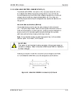
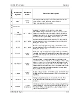
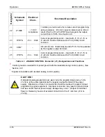
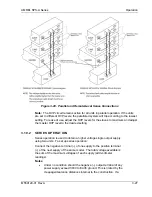
Following are Figure 3-8 with the connector's pin-out diagram, and Table
3–1 with ANALOG CONTROL connector designations and functions:
Figure 3-8. ANALOG CONTROL Connector (J1) Pin-out
Summary of Contents for AMREL SPS-A Series
Page 2: ......
Page 3: ......
Page 4: ......
Page 6: ...ii This page intentionally left blank ...
Page 8: ...iv This page intentionally left blank ...
Page 10: ...vi This page intentionally left blank ...
Page 16: ...CONTENTS AMREL SPS A Series vi M550129 01 Rev A This page intentionally left blank ...
Page 22: ...Overview AMREL SPS A Series 1 6 M550129 01 Rev A This page intentionally left blank ...
Page 42: ......
Page 71: ...AMREL SPS A Series Operation M550129 01 Rev A 3 29 This page intentionally left blank ...
Page 72: ......
Page 76: ...Maintenance AMREL SPS A Series 4 4 M550129 01 Rev A This page intentionally left blank ...