background image

7

B345403026PCOM

7

9 /12 

?? www.ameriwood.com ??

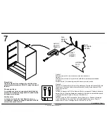
Please Note: 
The top of the unit is not shown for visibility of the 
safety bracket attachment. DO NOT remove the top of 
the unit. 
 
Observe por favor: 
La unidad de encima no demuestra la visibilidad del 
accesorio del soporte de seguridad. No quite la parte 
de encima de la unidad. 
 
Veuillez noter:
Le dessus de l'unité n'est pas illustré pour voir 
correctement l'attache du support de sûreté. NE PAS 
enlever le dessus de l'unité.


Option 2:
Drill a 3/16" diameter hole (5mm) in the wallboard. Tap the wall anchor(14d) into
the hole until it is flush. Fasten the wall bracket (14a) to the wall anchor (14d) 
with the screw (14c). 
Opcion 2:
Taladre un agujero de 3/16" de diámetro (5mm) en la pared. Golpea la ancla de
pared (14d) en el agujero hasta que sea parejo.  Abroche la escuadra de pared 
(14a) al la ancla de la pared (14d) con el tornillo (14c).
Option 2:
Percez un trou de 3/16" de diamètre (5 mm) dans le mur. Enfoncez l'ancrage 
mural (14d) dans le trou jusqu'à ce qu'il soit à égalité avec le mur. Fixez le 
support mural (14a) à l'ancrage mural (14d) avec la vis (14c).

Option 1;
Securely screw (14c) into solid area of the wall as shown. 
Opción 1; 
Firmemente el tornillo (14c) en el área sólida de la pared como mostrado.
L'option 1; 
Solidement vis (14c) dans région solide du mur comme montré.  

x

14

1


14c

14d

stud
montante

planche

wallboard

muro

mur

hole

agujero

trou

option 2
opción 2
l'option 2

option 1
opción 1
l'option 1

Summary of Contents for 5403026PCOM

Page 1: ... please visit our website or call our toll free customer service line We will gladly ship your replacement parts FREE of charge Si las partes están perdidas o dañadas Por favor visite nuestra página de Internet o llame a nuestra línea de teléfono gratis de Servicio al Cliente Nosotros le enviaremos sus repuestos sin cargo adicional serán totalmente gratis Si une pièce est manquante ou endommagée v...

Page 2: ......

Page 3: ...ssée 35403026050 3 drawer bottoms 3 cajones inferiores 3 fonds de tiroir 35403302081 back panel panel trasero panneau arriere K54030001 A B C D E F I J top cima dessus 35403026033 D bottom fondo fond 35403000040 F F G G G H H H I I I I I This piece is paperboard construction It is not made from wood but is required for the assembly of your unit Esto pedazo son la construcción del carton Ello no so...

Page 4: ...12b 12c x 9 24 A12610 3 4 pan head cabeza redondo 3 4 tête ronde 3 4 x 10 6 A12700 7 8 pan head cabeza redondo 7 8 tête ronde 7 8 x A22570 cam lock cerradura de leva serrure de came 1 8 x cam bolt A22510 perno de leva boulon de came 2 8 2 3 turn to fully lock se vuelven a totalmente cerradura tour pour verrouiller complètement 4 Tighten to fully seat Do not over tighten Apriétese a totalmente asie...

Page 5: ... 2 Proper orientation of CAM LOCK Posición correcta de la cerradura de leva Bonne orientation de la SERRURE DE CAME Titus STOP do not discard drawer stops they will be used later in the assembly ALSO no descartar las paradas del cajón porque serán utilizados mas tarde en el montaje ARRÉT ne pas jeter les butées de tiroir ils seront utilisés plus tard dans l assemblage ...

Page 6: ...6PCOM7 6 12 www ameriwood com x4 C 1 3 x4 x4 3 D D 2 1 1 Approx 7 16 3 Proper orientation of CAM LOCK Posición correcta de la cerradura de leva Bonne orientation de la SERRURE DE CAME Titus 14a 14b 2 x 14 1 14a 14b ...

Page 7: ...4 B345403026PCOM7 7 12 www ameriwood com x3 x6 4 5 5 5 4 D E E D A E B D D finished edge borde acabado bord fini finished edge borde acabado bord fini UNLOCK LOCK APRETAR DESAPRETAR OUVRIR SERRER Titus ...

Page 8: ...to the parts straight and Please make sure that the Backs are attached securely ADVERTENCIA AVERTISSEMENT WARNING Flush the edge of the back panel with the bottom edge of the bottom shelf Align squarely and nail straight through into back edges Alinie el borde del panel trasero con el borde inferior del estante inferior Alinee en ángulo recto y clave derecho dentro o en los bordes traseros Alignez...

Page 9: ...the wall anchor 14d with the screw 14c Opcion 2 Taladre un agujero de 3 16 de diámetro 5mm en la pared Golpea la ancla de pared 14d en el agujero hasta que sea parejo Abroche la escuadra de pared 14a al la ancla de la pared 14d con el tornillo 14c Option 2 Percez un trou de 3 16 de diamètre 5 mm dans le mur Enfoncez l ancrage mural 14d dans le trou jusqu à ce qu il soit à égalité avec le mur Fixez...

Page 10: ...IRMEMENTE NE FAITES PAS OVERTIGHTEN finished side lado terminado surface finie H x3 Slide the DRAWER BOTTOM H into the groove of the DRAWER SIDES and the DRAWER FRONT Desícese el FONDO DE CAJON H en la ranura de los LADOS DE CAJON y el FRENTE DE CAJON Glissez le FOND du TIROIR H dans la rainure du TIROIR SE MET et le TIROIR SE TROUVE F I I ...

Page 11: ...rface crue Note The DRAWER BOTTOM must insert into the groove in the DRAWER BACK G Nota El FONDO DE CAJON debe insertar en la ranura en el TRASERO DE CAJON G La note Le FOND du TIROIR doit insérer dans la rainure dans le TIROIR EN ARRIÈRE G x12 11 G 11 11 10 13 x3 x3 x6 x3 10 13 ...

Page 12: ...y o causar serias lesiones Ce meuble a été conçu pour supporter les charges maximales indiquées En excédant ces limites de charge le meuble pourrait devenir instable s effondrer et ou causer des blessures graves MAXIMUM LOADS CARGA MAXIMA CHARGES MAXIMALES Drawers must be 6 into the unit to insert STOP PINS 12c Los cajones deben ser 6 en la unidad insertar la PARADA FIJA 12c Les tiroirs doivent êt...

Reviews: