American Standard AUD2B060AFV32A Installer'S Manual Download Page 24

24

18-CD24D1-2

Installer’s Guide

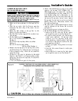
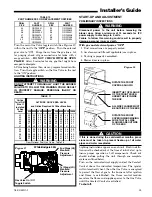
For complete shutdown: Turn the gas cock knob on the
main Gas Valve to the “OFF” position (See Figures 14 &
15).
Disconnect the electrical supply to the unit.

SEQUENCE OF OPERATION

NOTE: Whole House Air Cleaner is energized when
blower is operating and there is a call for heat or cool.
This can result in brief periods of blower operation
with the whole house air cleaner off.  This can occur
during the heat fan off period or if the enhanced
mode of operation is chosen for cooling.

Comfort Control call for heat (2-Stage Comfort Control)

Call for 1st Stage only:

W1 Comfort Control contacts close signaling the control
module to run its self-check routine. After the control
module has verified that the 1st Stage Pressure Switch
contacts are open and the Limit Switch(es) contacts are
closed, the draft blower will be energized.
As the induced draft blower comes up to speed, the
Pressure Switch contacts will close and the ignitor
warm up period will begin. The ignitor will heat for
approx. 20 seconds, then the Gas Valve is energized in
1st Stage to permit gas flow to the burners.
The flame sensor confirms that ignition has been
achieved within the 4 second ignition trial period.
As the flame sensor confirms that ignition has been
achieved, the delay to fan ON period begins timing and
after approx. 45 seconds the indoor blower motor will be
energized at low speed and will continue to run during
the heating cycle. The whole house air cleaner will en-
ergize.

Call for 2nd Stage after 1st Stage:

W2 Comfort Control contacts close signaling a call for
2nd Stage Heat. After a 30 second delay, the induced
draft blower will be energized on high speed and the
2nd Stage Pressure Switch contacts will close. The Gas
Valve is energized in 2nd Stage and the indoor blower
motor in high speed.

2nd Stage satisfied, 1st Stage still called:

W2 Comfort Control contacts open signaling that 2nd
Stage Heating requirements are satisfied.
The induced draft blower is reduced to low speed allow-
ing the 2nd Stage Pressure Switch contacts to open and
the Gas Valve is reduced to 1st Stage. The indoor
blower motor is reduced to low speed.

1st stage satisfied:

W1 Comfort Control contacts open signaling that 1st
Stage heating requirements are satisfied.  The Gas
Valve will close and the induced draft blower  and the
whole house air cleaner will be de-energized. The in-
door blower motor will continue to run for the fan off
period (Field selectable at 60, 100, 140 or 180 seconds),
then will be de-energized by the control module.

Comfort Control call for heat (1-Stage Comfort
Control)

W1/  W2 (jumpered) Comfort Control contacts close sig-
naling a call for heat. 1st Stage sequence of operation
remains the same as above. 2nd Stage Heat will ener-
gize after the Stage delay timer (10 minutes) has ex-
pired.

Comfort Control satisfied:

W1/  W2 (jumpered) contacts close signaling the control
module to close the Gas Valve. The induced draft blower
is switched to low speed and de-energized after the post
purge timer has expired.  The indoor blower motor will
continue to operate after the flames are extinguished
and then is switched to low heat speed for the FAN-
OFF period.  The whole house air cleaner will be de-en-
ergized.

NOTE TO INSTALLER

Review warnings and the contents of USER’S INFOR-
MATION MANUAL with the homeowner when installa-
tion is complete and equipment is ready to be turned
over to the homeowner for normal operation.

CONTROL AND SAFETY SWITCH
ADJUSTMENT

LIMIT SWITCH CHECK OUT

The limit switch is a safety device designed to close the
Gas Valve should the Furnace become overheated.
Since proper operation of this switch is important to the
safety of the unit, it 

must be checked out on initial

start up by the installer

.

To check for proper operation of the Limit Switches, set
the Comfort Control to a temperature higher than the
indicated temperature to bring on the Gas Valve.  Re-
strict the airflow by blocking the return air or by dis-
connecting the blower.  When the Furnace reaches the
maximum outlet temperature as shown on the rating
plate, the burners must shut off.  If they do not shut off
after a reasonable time and overheating is evident, a
faulty Limit Switch is probable and the Limit Switch
must be replaced.  After checking the operation of the
Limit Control, be sure to remove the paper or card-
board from the return air inlet, or reconnect the
blower.  Refer to the Service Facts for additional in-
structions.

INDOOR BLOWER TIMING

WARNING

!

DISCONNECT POWER TO THE UNIT BEFORE REMOV-
ING THE BLOWER DOOR.
FAILURE TO FOLLOW THIS WARNING COULD RESULT
IN PROPERTY DAMAGE, PERSONAL INJURY OR
DEATH

.

Summary of Contents for AUD2B060AFV32A

Page 1: ...degree or level of seriousness associated with a particular hazard The signal words for safety markings are WARNING and CAUTION a WARNING indicates a potentially hazardous situation which if not avoid...

Page 2: ...ected to the venting system properly vents where tested as outlined above return doors windows exhaust fans fireplace dampers and any other gas fired burning appliance to their previous conditions of...

Page 3: ...NET FAILURE TO FOLLOW THIS WARNING COULD RESULT IN PROPERTY DAMAGE PERSONAL INJURY OR DEATH 8 A gas fired Furnace for installation in a residential garage must be installed as specified in Location an...

Page 4: ...he builder or the installer However before the Furnace is moved into place be sure to consider the following requirements 1 Is the location selected as near the chimney or vent and as centralized for...

Page 5: ...e it must be installed so that the burners and the ig nition source are located not less than 18 inches above the floor and the Furnace must be located or protected to avoid physical damage from vehic...

Page 6: ...NSIONS ARE IN INCHES MODEL DIM A DIM B DIM C DIM D DIM E UD2B060AFV32A UD2B080AFV32A UD2B100AFV32A 17 1 2 9 5 8 16 1 4 16 16 UD2C080AFV42A 21 13 1 16 19 3 4 19 1 2 19 1 2 UD2D120AFV52A 24 1 2 15 5 16...

Page 7: ...tart up g Set furnace in place Repeat step a g in reverse or der Do Not put cardboard back in Furnace Inner blower door MUST be put back into place UPFLOW FURNACE CASED COIL SCREWS BOTH SIDES STANDOFF...

Page 8: ...e at least 32 in length to allow for access to service panels If the Furnace is suspended using steel strap it must be sup ported at all four corners and in the middle at the front of the Furnace Figu...

Page 9: ...Z223 1 or Sections 7 2 7 3 or 7 4 of CSA B149 1 Installation Codes and applicable provi sions of the local building codes Special conditions cre ated by mechanical exhausting of air and fireplaces mus...

Page 10: ...run full size from the Furnace to a location outside the utility room basement attic or crawl space Do NOT install return air through the back of the Fur nace cabinet Confined spaces are installations...

Page 11: ...re smoke or unsafe levels of carbon monoxide These devises should be listed by Underwriters Labo ratories Inc Standards for Single and Multiple Station Carbon Monoxide Alarms UL 2034 or CSA Interna ti...

Page 12: ...result in carbon monoxide poisoning or death NOTE The following section does not apply if BAYVENT800B Masonry Chimney Vent Kit is used All instructions with the kit must be followed GENERAL VENTING I...

Page 13: ...ow are desired for com fort use long fan cycles instead of continuous air flow 9 Apply other good venting practices as stated in the venting section of the National Fuel Gas Code ANSI Z223 1 latest ed...

Page 14: ...for thermostats requiring connection to transformer common terminal 11 Optional humidistat is to be connected between R and BK Factory installed jumper R to BK on the circuit board must be cut if opt...

Page 15: ...delays 9 Optional humidistat is to be connected between R and BK Factory installed jumper R to BK on the circuit board must be cut if optional humidistat is used The jumper must also be cut when apply...

Page 16: ...R SEE NOTE 9 FIELD ADDED JUMPER W1 TO W2 2ND STAGE WILL FIRE 10 MINUTES AFTER 1ST B C B C TO 115 V 1 PH 60 HZ POWER SUPPLY PER LOCAL CODES HUM SEE NOTE 5 FIELD WIRING DIAGRAM FOR VARIABLE SPEED 2 STAG...

Page 17: ...NOTE 9 W14 JUMPER SEE NOTE 9 From Dwg B342020 Rev 0 B C B C TO 115 V 1 PH 60 HZ POWER SUPPLY PER LOCAL CODES HUM SEE NOTE 5 FIELD WIRING DIAGRAM FOR VARIABLE SPEED 2 STAGE FURNACE 2 STAGE HEATING 1 ST...

Page 18: ...only non heat pump systems jumper Y to O for proper operation of the delay profiles and the Humidis tat For two compressor or two speed systems jumper Ylo to O The factory installed jumper between R...

Page 19: ...on with liquefied petroleum gases Refer to piping Table 6 for delivery sizes Connect gas supply to the unit using a ground joint union and a manual shut off Valve as shown in Figures 14 and 15 Nationa...

Page 20: ...JOINT GROUND UNION JOINT DRIP LEG DRIP LEG AIR FLOW AIR FLOW The Furnace must be isolated from the gas supply pip ing by closing its individual manual shut off Valve dur ing any pressure testing of th...

Page 21: ...To adjust the Manifold Pressure a Turn off all electrical power to the system b Attach a Manifold Pressure gauge to the outlet pressure tap marked OUT PRESS TAP on White Rodgers gas valve model 36G se...

Page 22: ...56 25 288 46 157 74 97 132 54 26 277 47 153 76 95 136 53 27 267 48 150 78 92 140 51 28 257 49 147 80 90 144 50 TABLE 8 FINAL MANIFOLD PRESSURE SETTINGS inches w c FUEL 2nd Stage Max 1st Stage Max NAT...

Page 23: ...he Gas Valve is energized to permit the flow of gas to the burners After ignition and flame is established the flame control module monitors the flame and supplies power to the Gas Valve until the Com...

Page 24: ...ling that 1st Stage heating requirements are satisfied The Gas Valve will close and the induced draft blower and the whole house air cleaner will be de energized The in door blower motor will continue...

Page 25: ...of 15 seconds for IFC power supply to discharge to 0 volts Failure to follow this warning could result in property damage personal injury or death WARNING Operation with the door removed or ajar can...

Page 26: ...OF FLAME If loss of flame occurs during a heating cycle or flame is not present at the sensor the flame control module will close the Gas Valve The flame control module will then recycle the ignition...

Page 27: ...ELD CHARGER CAUTION FIELD CHARGER PINS ARE SHARP DO NOT BEND FIELD CHARGER PINS WEAR APPROPRIATE GLOVES WHEN HANDLING THE FIELD CHARGER 1 Turn off the Comfort Control and the service dis connect 2 Tur...

Page 28: ...ELL GAS Do not try to light any appliance Do not touch any electrical switch do not use any phone in your building Immediately call your gas supplier from a neighbor s phone Follow the gas supplier s...

Page 29: ...edge the reset by turning on the Red LED for 2 seconds UX2 DX2 Integrated Furnace Control INTEGRATED FURNACE CONTROL GREEN STATUS LED FLASH CODES Flashing Slow Normal No call for Heat Flashing Fast No...

Page 30: ...ints are tight 6 Make sure secondary drain pan is installed 7 Check power supply for correct requirements per unit nameplate 8 Energize the system and carefully observe its op eration make any necessa...

Reviews: