


20
18-CD24D1-2
Installer’s Guide
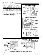
Figure 14
LEFT SIDE PIPING (STANDARD)
TOP VIEW OF RIGHT SIDE PIPING
RIGHT SIDE PIPING (OPTIONAL)
HORIZONTAL FURNACE GAS PIPING MAY BE FROM EITHER SIDE
(Typical UPFLOW Furnace in horizontal configuration shown)
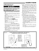
Figure 15
AUTOMATIC GAS VALVE
WITH MANUAL SHUTOFF
AUTOMATIC GAS VALVE
WITH MANUAL SHUTOFF
MAIN MANUAL
SHUTOFF VALVE
MAIN MANUAL
SHUTOFF VALVE
GROUND UNION
JOINT
GROUND UNION
JOINT
DRIP LEG
DRIP LEG
AIR FLOW
AIR FLOW
The Furnace must be isolated from the gas supply pip-
ing by closing its individual manual shut-off Valve dur-
ing any pressure testing of the gas supply piping system
at test pressures equal to or less than 1/2 psig (3.5 kPa).
NOTE: Maximum pressure to the Gas Valve for natural
gas is 13.8" W.C. Minimum pressure is 5.0" W.C. Maxi-
mum pressure to the Gas Valve for propane is 13.8"
W.C. Minimum pressure is 11.0" W.C.
All gas fittings must be checked for leaks using a soapy
solution before lighting the Furnace.
DO NOT
CHECK WITH AN OPEN FLAME!


