American Megatrends Apollo User Manual Download Page 34

28

Apollo  Motherboard User’s Guide

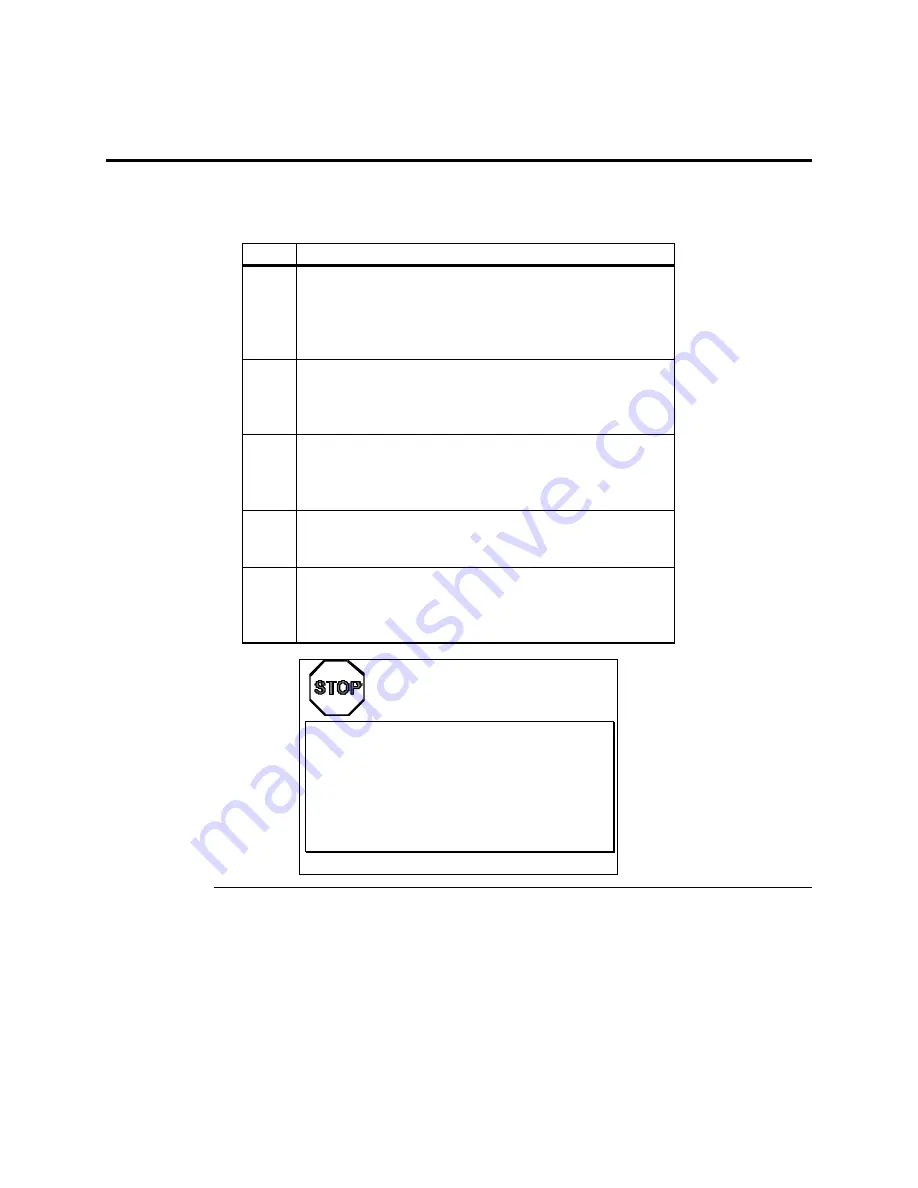
Step 5 Install the Motherboard

The motherboard mounting hole pattern is the same as the mounting hole pattern on the standard mini Baby
AT motherboard. Standoffs and mounting screws are not supplied with the motherboard. The chassis
manufacturer should supply these parts.

Step

Action

1

Place the chassis on an anti-static mat. Connect the chassis to
ground to avoid static damage during installation. Connect an
alligator clip with a wire lead to any unpainted part of the chassis.
Ground the other end of the lead at the same point as the mat and
the wristband.

2

Rotate the chassis so that the front is to the right, and the rear is
to the left. The side facing you is where the motherboard is
mounted. The power supply is mounted at the far end of the
chassis.

3

Hold the motherboard, component-side up, with the edge with the
SIMM sockets toward you and the edge with the power supply
connector away from you. The keyboard, mouse, and video
connectors should be to the left.

4

Carefully slide the motherboard into the chassis. Make certain that
the edge connectors fit the ports in the rear of the chassis. The
motherboard should rest level with the chassis.

5

Place the mounting screws in the holes provided for them and
tighten them. If necessary, shift the motherboard slightly to align
the mounting holes on the motherboard with the holes on the
chassis. See the drawing on the next page.

Warning

If using metallic screws, make sure that you use them

only in the plated mounting holes.

If using metallic screws, make sure that the head of the

screw fits completely inside the plated mounting holes.

See the graphic on the following page.

Cont’d

Summary of Contents for Apollo

Page 1: ...Apollo Pentium PCI ISA Motherboard User s Guide MAN 728 2 21 96 ...

Page 2: ...rd and Microsoft are registered trademarks of Microsoft Corporation SMC is a registered trademark of System Management Corporation IBM AT VGA PS 2 OS 2 and EGA are registered trademarks of International Business Machines Corporation XT and CGA are trademarks of International Business Machines Corporation Fujitsu is a registered trademark of Fujitsu America Inc Motorola is a registered trademark of...

Page 3: ... Step 8 Connect the Mouse Cable 33 Step 9 Connect Cables 34 Step 10 Connect Onboard I O 37 Step 11 Install Floppy Drive 39 Step 12 Install Hard Disk 41 Step 13 Install Adapter Cards 43 Step 14 Test and Configure 44 4 WINBIOS Setup 45 Section 1 Setup 48 Standard Setup 48 Advanced Setup 52 Chipset Setup 55 Power Management Setup 56 PCI PnP Setup 59 Peripheral Setup 62 Section 2 Utility 64 Section 3 ...

Page 4: ...his manual describes the specifications and features of the Apollo motherboard It explains how to assemble a system based on the Apollo motherboard and how to use the AMIBIOS that is specifically designed for this motherboard This manual is not meant to be read by the computer owner who purchases a computer with this motherboard It is assumed that you the computer manufacturer will use this manual...

Page 5: ... handling the motherboard Make sure you stand on an anti static mat when handling the motherboard Avoid contact with any component or connector on any adapter card printed circuit board or memory module Handle these components by the mounting bracket Packing List You should have received the following an Apollo Pentium PCI ISA motherboard several cables a Warranty Card and The American Megatrends ...

Page 6: ...vi Apollo Motherboard User s Guide ...

Page 7: ...or 133 MHz The Intel Triton chipset on the motherboard optimizes the PCI local bus interface allowing the CPU to sustain the highest possible bandwidth at all times This motherboard includes four PCI and four ISA expansion slots Onboard I O includes IDE on the PCI local bus two serial ports and a parallel port Apollo Dimensions The Apollo Pentium PCI motherboard is approximately 8 inches wide by 1...

Page 8: ...CPU voltages are supported through a built in voltage regulator Programmable Crystal Oscillator The Apollo motherboard has a programmable crystal oscillator that supports all possible motherboard frequencies Supported CPU Voltages This motherboard supports standard VR and VRE voltages Voltages are selected through jumper settings CPU Cooling A heat sink or a heat sink and fan are required for ever...

Page 9: ...MB L2 Secondary 256 KB 64 MB L2 Secondary 512 KB 128 MB Cache Access Times The access times for L2 secondary cache memory are Host Clock Rate Asynchronous SRAM Access Time 50 MHz 15 ns 60 MHz 15 ns 66 66 MHz 15 ns CMOS RAM The Apollo Pentium PCI motherboard has 128 bytes of nonvolatile CMOS RAM NVRAM to store system configuration information Real Time Clock The Apollo motherboard has a real time c...

Page 10: ...ge mode or EDO memory types are supported and can be used together in the same memory bank SIMM Types The Apollo Pentium PCI motherboard supports EDO or fast page mode SIMMs operating at 70 ns RAS access time Memory must be populated two SIMMs at a time The SIMMs can be single sided or double sided Both x 32 and x 36 SIMMs are supported The following SIMM types can be used 512 KB x 32 or 36 1 MB x...

Page 11: ...pport allows you to boot the computer from a CD ROM drive provides ATA IDE Mode programming support provides an icon in WINBIOS Setup that displays system information and supports the Extended Capabilities Port ECP and Enhanced Parallel Port EPP specifications The system BIOS is stored at E0000h FFFFFh and has a built in WINBIOS Setup for system configuration WINBIOS Setup has a graphical user int...

Page 12: ... four pin berg connector is provided on the motherboard to attach a keyboard lock cable Speaker The motherboard has a standard speaker attachment CMOS RAM Drain The motherboard includes a two pin berg JCP Password Clear that can be shorted to drain all power from CMOS RAM This jumper can be used if the computer is password protected and the user has forgotten the password Fuse The motherboard incl...

Page 13: ... is supported on 2 88 MB floppy drives Onboard IDE The two onboard IDEcontrollers are on the PCI local bus The IDE controllers support IDE Modes 0 1 2 3 and 4 and up to four IDE drives Two standard 40 pin IDE connectors are on the motherboard IDE bus mastering 32 bit transfer LBA mode and fast ATA are supported The cycle times for the IDE modes are IDE Mode Cycle Time in nanoseconds 0 600 1 383 2 ...

Page 14: ...ny DMA channel can be set for 8 or 16 bit DMA device sizes Fifteen Interrupt Levels The NMI takes precedence over all 15 hardware interrupts Priority Label Typical Interrupt Source 1 IRQ 0 Interval Timer 1 Counter 0 OUT 2 IRQ 1 Keyboard 3 10 IRQ 2 Used internally for IRQ 8 through IRQ 15 3 IRQ 8 Real Time Clock 4 IRQ 9 PCI PnP or ISA 5 IRQ 10 PCI PnP or ISA 6 IRQ 11 PCI PnP or ISA 7 IRQ 12 Onboard...

Page 15: ...the PC is idle Compliance with EPA Green PC Specifications To meet the Green PC specifications a computer system must be able to enter an idle state Sleep Mode that reduces the total system power use to 30 watts or less on the input AC side The monitor and printer must also use no more than 30 watts Responsibility The system integrator is ultimately responsible for meeting all Green PC specificati...

Page 16: ...n that requires long periods of CPU activity with no input from the keyboard mouse COM1 or COM2 Sleep Mode should be disabled in WINBIOS Setup If Sleep Mode is not disabled the system will switch to Sleep Mode and the system performance will be greatly decreased Some examples of such applications are file servers CAD systems software compilers screen savers and many more No Need for Screen Savers ...

Page 17: ...rd set of interface architecture timings electrical and physical specifications that permit all PCI local bus products to be totally interchangeable PCI is a multiplexed extension of the CPU bus In PCI the CPU bus control mechanisms have been extended to optimize I O support PCI establishes a local bus standard where a large variety of I O components can be directly connected without using any glu...

Page 18: ...t data path has low latency for random accesses about 60 ns write access latency to slave registers from a PCI bus master on the PCI bus is capable of full concurrency with the processor and PCI bus masters has full multimaster capability allowing any PCI Master peer to peer access to any PCI slave has hidden and overlapped central arbitration has a low pin count master 47 slave 45 has address and...

Page 19: ...r rate improvements can be achieved without splitting resource utilization between the CPU and a bus mastering device Peripheral devices can operate at speeds up to 33 MHz in a PCI environment Burst Mode The PCI specification also provides for burst mode of any length for both reads and writes Multiplexing PCI is a multiplexed bus Multiplexing allows more than one signal to be sent on the same ele...

Page 20: ...14 Apollo Motherboard User s Guide ...

Page 21: ...all motherboard Page 28 5 Connect the power supply Page 30 6 Connect the keyboard Page 32 7 Connect the mouse Page 33 8 Connect cables Page 34 9 Connect onboard I O Page 37 10 Install floppy disk drives Page 39 11 Install IDE hard disk drives Page 40 12 Install riser card and adapter cards Page 43 13 Test and configure Page 44 Warning This motherboard contains sensitive electronic components which...

Page 22: ...16 Apollo Motherboard User s Guide Apollo Motherboard Layout ...

Page 23: ...he anti static mat Similarly a strip of conductive aluminum foil wrapped around the wrist and grounded through a 1 megohm resistor serves the same purpose as the wristband 3 Inside the carton the motherboard is packed in an anti static bag and sandwiched between sheets of sponge Remove the sponge and the anti static bag Place the motherboard on a grounded anti static surface component side up Save...

Page 24: ...mpers or by removing the shorting bridge entirely When the jumper has no shorting bridges installed on it it is said to be OPEN The jumper descriptions instruct you to short Pins 1 2 or Pins 3 4 etc Pin 1 is always identified by a 1 printed on the motherboard Pins are numbered consecutively Important Do not change any jumper settings that are not described in this manual The Apollo motherboard has...

Page 25: ...OM Power Supply J12 Hardware Reset JCP Clear CMOS RAM J3 Processor Pipeline Mode J8 Bus to Processor Speed Ratio JVR Processor Voltage JK3 Processor Clock Rate JK2 Processor Clock Rate JK1 Processor Clock Rate J5 ISA Bus Clock Rate J1 Caching MethodJ1 is a three pin berg Short pins 1 2 to select Write Through caching as shown below Leave J1 OPEN to select Write Back caching this is the factory set...

Page 26: ...wer J4 is a three pin berg that selects the type of power provided to the Flash ROM Short pins 1 2 to select 12V Short Pins 2 3 to select 5V the factory setting See the drawing on page 16 for the J4 location J12 Hardware ResetJ12 is a two pin single inline berg Short J12 to reset the system J3 CPU Pipeline Mode J3 is a two pin single inline berg Short J3 to enable CPU pipeline mode factory setting...

Page 27: ... Press Del to run WINBIOS Setup Load the Optimal default settings by clicking on the Optimal icon on the WINBIOS Setup screen see page 47 8 Modify the WINBIOS Setup Standard Setup Advanced Setup Chipset Setup Power Management Setup and Peripheral Setup options as appropriate 9 Choose Save and Exit when leaving WINBIOS Setup J8 Bus CPU Speed Ratio J8 is a two pin berg that specifies the ratio betwe...

Page 28: ...d CPU Type Clock J5 Setting Intel P54C A80502 75 PCLK 3 Short Pins 1 2 Intel P54C A80502 90 Intel P54C A80502 100 PCLK 4 Short Pins 2 3 Intel P54CQS A80502 120 PCLK 4 Short Pins 2 3 Step 3 Install Memory The main memory subsystem on the Apollo Pentium PCI motherboard has four 32 bit SIMM Single Inline Memory Module memory sockets arranged in two memory banks The motherboard supports 8 to 128 MB of...

Page 29: ... MB 16 MB 16 MB 8 MB 8 MB 48 MB 16 MB 16 MB 8 MB 8 MB 64 MB 32 MB 32 MB None None 64 MB 32 MB 32 MB 1 MB 1 MB 66 MB 32 MB 32 MB 4 MB 4 MB 72 MB 32 MB 32 MB 8 MB 8 MB 80 MB 32 MB 32 MB 16 MB 16 MB 96 MB 32 MB 32 MB 32 MB 32 MB 128 MB MemorySystem memory is reported by AMIBIOS as it boots and again when the AMIBIOS System Configuration Screen is displayed Memory displayed on the System Configuration...

Page 30: ...M36256S 70 Oki MSC2320A 70YS9 PNY P36256 70 Samsung KMM536256B 7 1 MB x 36 Micron MT12D136M 7 Mitsubishi MH1M36ADJ 7 PNY P361000 70 Motorola MCM36100AS 70 Oki MSC2355 70YS12 Samsung KMM5361000AV 7 4 MB x 36 Micron MT12D436M 7 Mitsubishi MH4M36SAJ 7 Motorola MCM36400S 70 PNY P364000 70 Samsung KMM5364100 7 8 MB x 36 Motorola MCM36800S 70 PNY P368000 707 Samsung KMM5368100 7 Cont d ...

Page 31: ...B x 32 or 36 1 MB x 32 or 36 4 MB x 32 or 36 8 MB x 32 or 36 or 16 MB x 32 or 36 SIMMs Place the motherboard on an anti static mat With the component side of the SIMM facing you firmly push the SIMM into the socket at an angle then push it up When properly inserted the SIMM clicks into place as the latching pins engage The SIMM installation process is shown below A SIMM looks like this ...

Page 32: ...ro insertion force CPU socket is near one edge of the motherboard as shown on the drawing on page 16 Warning Improper CPU installation can damage the CPU and the motherboard You must follow the procedures in this section exactly as documented Make sure you wear an antistatic wristband while installing the CPU Follow all antistatic procedures Step Action 1 Lift the lever on the ZIF socket The empty...

Page 33: ...CPU Check for bent pins on the CPU Gently straighten any bent pins with pliers Place the CPU in the middle of the socket as shown below Make sure that pin 1 of the CPU is aligned with pin 1 of the socket Make sure you are properly grounded while handling the CPU 3 Complete installation by lifting the ZIF lever to the other side of the socket as shown below ...

Page 34: ...d The power supply is mounted at the far end of the chassis 3 Hold the motherboard component side up with the edge with the SIMM sockets toward you and the edge with the power supply connector away from you The keyboard mouse and video connectors should be to the left 4 Carefully slide the motherboard into the chassis Make certain that the edge connectors fit the ports in the rear of the chassis T...

Page 35: ...Chapter 3 Installation 29 Step 5 Install Motherboard Continued ...

Page 36: ... and must be set usually via a switch to the proper range Use at least a 200 watt power supply which should have built in filters to suppress radiated emissions Connect Power Cables Attach the power supply cables to the power connector CN1 on the motherboard AT compatible power supplies have two six pin connectors attached as shown below The six pin connector on the power cable with three red wire...

Page 37: ... cut to fit on some power supplies as shown below CN1 Pinout Pin Description 1 Power Good Orange wire Not used 2 VCC Red wire 3 12 Volts Yellow wire 4 12 Volts Blue wire 5 Ground Black wire 6 Ground Black wire 7 Ground Black wire 8 Ground Black wire 9 5 Volts White wire 10 VCC Red wire 11 VCC Red wire 12 VCC Red wire ...

Page 38: ...lo Motherboard User s Guide Step 7 Connect the Keyboard Cable The keyboard attaches via a standard six pin DIN keyboard connector CN2 Pin Assignments 1 Keyboard data 2 N C 3 Ground 4 Vcc 5 Keyboard clock 6 N C ...

Page 39: ... Attach the standard 9 pin mouse connector at the other end of the mouse cable to the mouse connector port on the computer case Incorrect mouse installation can cause the system to hang The motherboard mouse connector and cable connector pinouts are Motherboard Mouse Connector Pins Pin Assignments Corresponding Cable Connector Pins 1 Mouse data 9 2 N C 6 3 Ground 5 4 Vcc 5V 8 5 Mouse clock 1 ...

Page 40: ...connector with the same color coded wires If so follow the wire to the switch or LED Pin 1 is always indicated on the motherboard as shown below List of Connectors The following cables should be connected to the motherboard CPU fan cable to J11 optional external battery to J6 Reset Switch cable to J12 Speaker cable to J13 Keyboard Lock Power LED cable to J14 IDE LED Activity Indicator LED cable to...

Page 41: ...to an externally mounted reset switch When the reset switch is pressed the system performs a hard reset Pin 1 is ground and Pin 2 is Hard Reset Speaker Connector J13 J13 is a four pin single inline berg that is optionally attached via a cable to a standard system speaker AMIBIOS signals hardware problems through the speaker Pin 1 on the motherboard is identified by the arrow on the white box aroun...

Page 42: ...he user to lock the keyboard Pin 1 on the motherboard is identified Pin Description 1 LED power 2 LED power 3 Ground 4 Keyboard Lock 5 Ground IDE Indicator LED JP1 JP1 is a two pin berg that is attached via a cable to the externally mounted IDE Activity LED This LED lights when the IDE drive is running Warning In some IDE drives you may have to disable the IDE LED mounted on the drive by changing ...

Page 43: ...scribed on page 39 Conflicts AMIBIOS minimize conflicts between onboard and offboard I O devices AMIBIOS automatically checks the adapter cards installed in the expansion slots on the Apollo motherboard for a hard disk or floppy controller and serial or parallel ports COM1 and COM2 These are 10 pin bergs that provide an AT compatible serial port interface The serial port pinouts are Pin Signal Des...

Page 44: ... port connector is a 26 pin berg The pinout is shown below Pin Signal Description 1 STROBE 2 PD0 3 PD1 4 PD2 5 PD3 6 PD4 7 PD5 8 PD6 9 PD7 10 ACK 11 BUSY 12 PE 13 SLCT 14 AUTOFD 15 ERROR 16 INIT 17 SLCTIN 18 Ground 19 Ground 20 Ground 21 Ground 22 Ground 23 Ground 24 Ground 25 Ground Cont d ...

Page 45: ...r cannot be used if a hard disk adapter card with floppy controller is installed The motherboard supports up to two 720 KB 1 44 MB or 2 88 MB 3 drives and 360 KB and 1 2 MB 5 drives The connecting cable is a 34 pin ribbon connector with two 34 pin edge connectors for attaching the floppy disk drives There is a small twist in the cable between the floppy connectors The last end connector should be ...

Page 46: ...ND 6 DRATE0 7 GND 8 INDEX 9 GND 10 MOTOR0 11 GND 12 FDSEL1 13 GND 14 FDSEL0 15 GND 16 MOTOR1 17 GND 18 DIR 19 GND 20 STEP 21 GND 22 WDATA 23 GND 24 WGATE 25 GND 26 TRK0 27 GND 28 WRPROT 29 GND 30 RDATA 31 GND 32 HDSEL 33 GND 34 DSKCHNG Twist in Floppy Cable Floppy B to A Floppy B to A Floppy B to A Floppy B to A 10 to 16 12 to 14 14 to 12 16 to 10 11 to 15 13 to 13 15 to 11 ...

Page 47: ...y slave IDE drives must be connected by cable as shown below The IDE connectors are 40 pin dual inline bergs This motherboard supports IDE Modes 0 1 2 3 and 4 IDE prefetch LBA Logical Block Address mode high capacity drives over 528 MB 32 bit data transfer and fast IDE transfer These IDE features are configured in Peripheral Setup in WINBIOS Setup Disable the onboard IDE interface in Peripheral Se...

Page 48: ...DATA15 19 GND 20 KEY N C 21 N C 22 GND 23 IOW 24 GND 25 IOR 26 GND 27 IDERDY 28 ALE 29 N C 30 GND 31 INT14 32 IOCS16 33 HA1 34 N C 35 HA0 36 HA2 37 CS0 38 CS1 39 IDEACT 40 GND Secondary IDE Controller The secondary IDE connector is a 40 pin dual inline berg that connects the secondary primary and slave IDE drives to the secondary onboard IDE controller Attach the secondary master and slave IDE dri...

Page 49: ...DATA1 16 DATA14 17 DATA0 18 DATA15 19 GND 20 KEY N C 21 N C 22 GND 23 IOW 24 GND 25 IOR 26 GND 27 IDERDY 28 ALE 29 N C 30 GND 31 INT15 32 IOCS16 33 HA1 34 N C 35 HA0 36 HA2 37 CS2 38 CS3 39 N C 40 GND Step 13 Install Adapter Cards The Apollo Pentium PCI motherboard has four PCI expansion slots and four ISA expansion slots PCI adapter cards are automatically configured by AMIBIOS The ISA expansion ...

Page 50: ...egatrends Technical Support at 770 246 8645 if there are problems BIOS Errors If the system operates normally a display should appear on the monitor The BIOS Power On Self Test POST should execute If POST does not run successfully it will beep or display error messages Beeps indicate a serious problem with the system configuration or hardware The Beep Code indicates the problem AMIBIOS Beep Codes ...

Page 51: ... when the computer is powered on The system parameters are configured by a system BIOS Setup utility Historically BIOS Setup utilities have been character based required keyboard input and have had user interfaces that were not very intuitive New BIOS Setup Utility American Megatrends has now made available a new type of system BIOS Setup utility WINBIOS Setup has a graphical user interface that p...

Page 52: ...o perform an operation in the selected field Using the Keyboard with WINBIOS Setup WINBIOS Setup has a built in keyboard driver that uses simple keystroke combinations Keystroke Action Tab Change or select a global field Change or select the current field Enter Perform an operation in the current field Increment a value Decrement a value Esc Abort any window function PgUp Return to the previous pa...

Page 53: ...Setup main windows are Setup described in Section 1 on page 48 this section has up to six icons that permit you to set system configuration options such as date time hard disk type floppy type and many others parameters Utilities described in Section 2 beginning on page 64 has four icons that perform system functions Security described in Section 3 beginning on page 65 has two icons that control A...

Page 54: ... Choose these icons to configure the hard disk drive named in the option When you click on an icon the following parameters are listed Type LBA Large Mode Block Mode 32Bit Mode and PIO Mode All parameters relate to IDE drives exceptType Configuring an MFM Drive If configuring an old MFM hard disk drive you must know the drive parameters number of heads number of cylinders number of sectors the sta...

Page 55: ...rite Precompensation The size of a sector gets progressively smaller as the track diameter diminishes Yet each sector must still hold 512 bytes Write precompensation circuitry on the hard disk compensates for the physical difference in sector size by boosting the write current for sectors on inner tracks This parameter is the track number where write precompensation begins Landing Zone This number...

Page 56: ... greater than 528 MB Click on Block Mode and choose On to support IDE drives that use Block Mode Click on 32Bit Mode and click on On to support IDE drives that permit 32 bit accesses Click on PIO Mode to select the IDE Programmed I O mode The settings are Auto 0 1 2 3 4 or 5 Click on Auto to allow AMIBIOS to automatically choose the PIO mode that the IDE drive being configured uses If you select 0...

Page 57: ...2 1023 17 60 MB 20 733 5 300 732 17 30 MB 21 733 7 300 732 17 43 MB 22 733 5 300 733 17 30 MB 23 306 4 0 336 17 10 MB 24 925 7 0 925 17 54 MB 25 925 9 65535 925 17 69 MB 26 754 7 754 754 17 44 MB 27 754 11 65535 754 17 69 MB 28 699 7 256 699 17 41 MB 29 823 10 65535 823 17 68 MB 30 918 7 918 918 17 53 MB 31 1024 11 65535 1024 17 94 MB 32 1024 15 65535 1024 17 128 MB 33 1024 5 1024 1024 17 43 MB 34...

Page 58: ...hat the AMIBIOS attempts to boot from after AMIBIOS POST completes The settings are C A CDROM CDROM C A or A C CDROM The default settings are C A CDROM BootUp NumLock Set this option to Off to turn the Num Lock key off when the computer is powered on and booted so you can use the arrow keys on both the numeric keypad and the keyboard The settings are On or Off The default settings are On Floppy Dr...

Page 59: ...ngs are Enabled or Disabled The default settings are Disabled Internal Cache This option specifies the caching algorithm used for L1 internal cache memory The settings are Setting Description Disabled Neither L1 internal cache memory on the CPU or L2 secondary cache memory is enabled WriteBack default Use the write back caching algorithm WriteThru Use the write through caching algorithm External C...

Page 60: ...hadow CC00 16K Shadow D000 16K Shadow D400 16K Shadow D800 16K Shadow C000 16K ShadowThese options control the location of the contents of the 16KB of ROM beginning at the specified memory location The settings are Setting Description Shadow The contents of C0000h C3FFFh are written to the same address in system memory RAM for faster execution Cache The contents of C0000h C3FFFh are written to the...

Page 61: ...r 15 16MB The default setting is Disabled DRAM Speed Specify the RAS access speed of the SIMMs installed in the motherboard as system memory The settings are 60ns or 70 ns The default is 70ns Caution If you have installed SIMMs with different speeds in the motherboard select the speed of the slowest SIMM You must always use SIMMs thathave the same speed within a memory bank ...

Page 62: ...fault settings are Disabled Green PC Monitor Power State This option specifies the power management state that the Green PC compliant video monitor enters after the specified period of display inactivity has expired The settings are Disabled Off Standby or Suspend The default settings are Disabled Video Power Down Mode This option specifies the power management state that the video subsystem enter...

Page 63: ...urtailed The settings are Disabled 1 Min 2 Min and all one minute intervals up to and including 15 Min The default settings are Disabled Slow Clock Ratio This option specifies the speed at which the system clock runs in power saving modes The settings are expressed as a ratio between the normal clock speed and the power down clock speed The settings are 1 1 1 2 half as fast as normal 1 4 the norma...

Page 64: ...13 IRQ 14 IRQ 15 These options enable event monitoring When the computer is in a power saving mode activity on the named interrupt request line is monitored by AMIBIOS When any activity occurs the computer enters Full On mode Each of these options can be set toMonitor or Ignore The default setting for all options is Ignore ...

Page 65: ...tion sets latency on the PCI local bus The settings are in units equal to PCI clocks The settings are 32 64 96 128 160 192 224 or 248 The Optimal and Fail Safe default setting is 64 PCI VGA Palette Snoop This option must be set to Enabled if any ISA adapter card installed in the computer requires VGA palette snooping The settings are Disabled or Enabled The Optimal and Fail Safe default settings a...

Page 66: ...ng for this option The default settings are Auto Offboard PCI IDE Primary IRQ This option specifies the PCI interrupt used by the primary IDE channel on the offboard PCI IDE controller The settings are Disabled INTA INTB INTC or INTD The default settings are Disabled Offboard PCI IDE Secondary IRQ This option specifies the PCI interrupt used by the secondary IDE channel on the offboard PCI IDE con...

Page 67: ...rea The settings are Disabled 16K 32K or 64K The Optimal and Fail Safe default settings are Disabled Reserved Memory Address This option specifies the beginning address in hex of the reserved memory area The settings are C0000 C4000 C8000 CC000 D0000 D4000 D8000 or DC000 The Optimal and Fail Safe default settings are C0000 ...

Page 68: ...rboard and specifies the base I O port address for serial port 1 The settings are 3F8h 3E8h or Disabled The Optimal default setting is 3F8h The Fail Safe default setting is Disabled Onboard Serial Port2 This option enables serial port 2 on the motherboard and specifies the base I O port address for serial port 2 The settings are 2F8h 2E8h or Disabled The Optimal default setting is 3F8h The Fail Sa...

Page 69: ... parallel port signals to provide asymmetric bidirectional data transfer driven by the host device ECP The parallel port can be used with devices that adhere to the Extended Capabilities Port ECP specification ECP uses the DMA protocol to achieve transfer rates of approximately 2 5 Mbs ECP provides symmetric bidirectional communications Parallel Port DMA This option is only available if the settin...

Page 70: ...board User s Guide Section 2 Utility The following icons appear in this section Color Set sets the WINBIOS Setup screen colors Language allows you to select English German or French language screen prompts and messages ...

Page 71: ... by choosing either Always the password prompt appears every time the system is powered on or Setup the password prompt appears only when WINBIOS is run The password is stored in CMOS RAM When you select Supervisor or User AMIBIOS prompts for a password You must set the Supervisor password before you can set the User password Enter a 1 6 character password The password does not appear on the scree...

Page 72: ...ssword confirmation is incorrect an error message appears If the new password is entered without error press Esc to return to the WINBIOS Main Menu The password is stored in CMOS RAM after WINBIOS completes The next time the system boots you are prompted for the password if the password function is present and is enabled Remember the Password Keep a record of the new password when the password is ...

Page 73: ...or of the hard disk drive The settings are Enabled or Disabled If enabled the following appears when a write is attempted to the boot sector You may have to type N several times to prevent the boot sector write Boot Sector Write Possible VIRUS Continue Y N _ The following appears after any attempt to format any cylinder head or sector of any hard disk drive via the BIOS INT 13 Hard Disk Drive Serv...

Page 74: ...n WINBIOS Setup when you first began this WINBIOS Setup session Optimal You can load the optimal default settings for the WINBIOS by selecting the Optimal icon The Optimal default settings are best case values that should optimize system performance If CMOS RAM is corrupted the Optimal settings are loaded automatically Fail Safe You can load the Fail Safe WINBIOS Setup option settings by selecting...

Page 75: ... 69 5 Jumper Settings for Commonly Used CPUs The Apollo motherboard supports several types of Intel Pentium CPUs Jumpers JK1 JK2 JK3 JV and J8 must be set for each CPU The following drawings illustrate the jumper settings for some common CPUs Cont d ...

Page 76: ...70 Apollo Motherboard User s Guide Jumper Settings for Commonly Used CPUs Continued ...

Page 77: ... 61M256AH DIP 5V 3 3V 5V Mix ISSI 32 x 8 61LV256 DIP 3 3V 3 3V Pure Upgrade Steps Step Action 1 Turn the system off If the motherboard is already installed in a computer case remove the cover and expose the motherboard 2 Make sure you are properly grounded to prevent electrostatic discharge Removethe DIPs in sockets M1 through M8 See the drawing on the previous page for the M1 through M8 locations...

Page 78: ...ntinued Jumper Settings The jumpers that control secondary cache memory JPW1 JPW2 JPW3 JPW4 J9 J10 and JC1 are shown below These jumpers are near the CPU The jumper settings for 256 KB mixed voltage 256 KB 3 3V and 512 KB 3 3V cache memory are shown below Cont d ...

Page 79: ...er Reinstall the computer cover and turn system power on The system BIOS should now report 512 KB of secondary cache memory now after the computer boots If it does not repeat the cache memory installation procedure above Using only 256 KB If using 256 KB of secondary cache memory 32 KB x 8 SRAMDIPs should be installed in M1 through M8 An 8 KB x 8 5V SRAM DIP should be installed in M9 Pins 1 2 of J...

Page 80: ...74 Apollo Motherboard User s Guide ...

Page 81: ... to reprogram the Flash EPROM based AMIBIOS The bootblock code immediately reads the A drive looking for the new BIOS information 4 When the flash ROM has successfully been programmed the computer will reboot Boot Block BIOS Actions When you reprogram from system boot the boot block BIOS code Reads S728P ROM from the root directory of the floppy disk in drive A Erases the Flash EPROM Programs the ...

Page 82: ...o read from floppy drive A 2 Look for S728P ROM on the floppy disk S728P ROM must be in the root directory of the floppy disk in drive A There is no beep if successful 3 Read the floppy disk The floppy disk is read There is no beep if this step is successful 4 Check for BIOS file size The BIOS file size is checked There is no beep if this step is successful 5 Check for Flash EPROM The BIOS looks f...

Page 83: ...eep codes and when they can occur are Number of Beeps Description 1 Insert diskette in floppy drive A 2 The AMIBOOT ROM file was not found in the root directory of the diskette in floppy drive A 3 Base memory error 4 Flash program successful 5 Floppy read error 6 Keyboard controller BAT command failed 7 No Flash EPROM detected 8 Floppy controller failure 9 Boot Block BIOS checksum error 10 Flash e...

Page 84: ...f any E9h Program the CPU clock dependent chip set parameters EAh Enable the timer and the floppy diskette interrupt Enable the internal cache Copy the boot block BIOS and pass control to the boot block BIOS in the 0000h segment EDh Initialize the floppy drive EEh Look for a diskette in drive A Read the first sector of the diskette EFh Floppy read error F0h Search for AMIBOOT ROM in the root direc...

Page 85: ...ectors Expansion slots 42 Floppy disk 38 IDE Hard Disk Drive 40 Keyboard 32 Reset Switch 34 Serial ports 36 SIMM 25 CPU Installing 26 CPU Voltages 2 D Date Time Setup option 48 Default Settings WINBIOS Setup 68 Dimensions 1 Display Activity 57 DMA Channels 8 DRAM Speed 55 E Expansion Slots 5 External Cache 53 F Fail Safe BIOS Setup Settings WINBIOS Setup 68 Figures Floppy drive cable 38 Floppy dri...

Page 86: ... J12 Reset 34 J2 Display Type 20 J3 CPU Pipeline Mode 20 J4 Flash ROM Power 20 J44 Green PC Power 33 J5 Bus Clock 22 J6 External Battery 34 J8 Bus CPU Speed Ratio 21 JCP Memory Drain 21 JK3 JK2 JK1 CPU Speed 22 JP1 35 Jumper Settings For CPUs 69 Jumpers 18 19 JVR CPU Voltage 21 K Keyboard 6 Keyboard Cable 32 Keyboard connector 32 Keyboard Lock J14 35 L Landing Zone 49 Language 64 Local Bus 6 M Mem...

Page 87: ...8 Processor Type 2 Programmable Crystal Oscillator 2 PS 2 type mouse 32 Q Quick Boot 52 R Real Time Clock 3 Reporting Memory 23 Reserved Memory Address 61 Reserved Memory Size 61 Resource conflicts 36 S S725P ROM 76 S728P ROM 76 Screen savers 10 Sec Master 48 Sec Slave 48 Secondary IDE Controller 41 Serial port Pinout 36 Serial Port 1 Select 20 SIMM Part Numbers 24 SIMM Types 4 SIMMs Installing 25...

Page 88: ...82 Apollo Motherboard User s Guide U Unpack the Motherboard 17 Utility WINBIOS Setup 64 V Video Power Down Mode 56 W WINBIOS Setup 45 Write Precompensation 49 ...

Reviews: