

1-30
American-Lincoln
®
SC7740
C1539/0002
SERVICE INSTRUCTIONS - Cont.
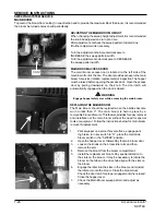
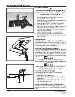
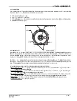
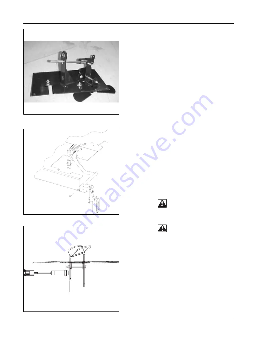
NEUTRAL ADJUSTMENT
NOTE
Orientation of the transmission arm assembly depends
upon which engine is installed in the SC7740 Sweeper
Scrubber. Adjustment directions given are as seen from the
operator’s position in the driver’s seat.
1.
Check engine no load RPM; SC7740, 2050 RPM.
Check hydraulic reservoir oil level.
2.
Raise the rear of the machine onto jack stands so the
rear wheel is off the ground.
3.
Loosen the jam nut away from the adjustment nut.
4.
If the rear drive wheel is turning forward, turn the
adjustment nut counterclockwise (this will lengthen the
threaded shaft). If the rear drive wheel is turning in
reverse, turn the adjustment nut clockwise (this will
shorten the threaded shaft).
5.
Tighten the jam nut against the threaded shaft.
6.
Test for operation of neutral with the engine at full
throttle. If the rear drive wheel turns, repeat adjustment
steps 3, 4 and 5.
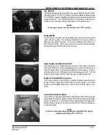
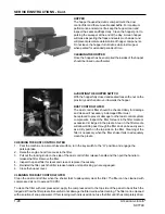
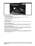
PARKING BRAKES
The parking brakes are located on the front wheels. They are
operated by the brake pedal and the lock lever. Check the
parking brakes daily for proper operation and inspect the brake
pads for wear every 100 hours of operation.
ADJUSTING THE PARKING BRAKE PEDAL
Perform this adjustment to ensure proper pedal height and
linkage operation. The brakes are properly adjusted when
the brakes hold theSC7740 on an 6-degree ramp. The brakes
need adjusted if the pedal travels closer than one inch to the
floor of the operator’s compartment when the brakes are fully
engaged.
WARNING
The hopper could fall and cause serious injury.
Always engage the hopper safety arm before working under
the hopper.
WARNING
Always park on a level surface, chock tires and observe
safety procedures when adjusting the brakes.
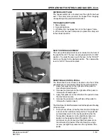
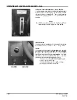
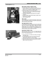
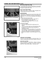
ADJUSTING THE PARKING BRAKES
When adjusting the brake clevis, follow these steps:
1.
Open cover.
2.
Remove pin from clevis (U-joint).
3.
Adjust clevis clockwise to tighten brakes for maximum
engagement.
4.
With parking brake “off”, rotate wheel with minimum
drag. (Not completely free)
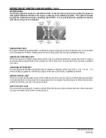
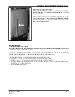
ADJUSTING THE DIRECTIONAL CONTROL SWITCH
With the foward/reverse pedal in the neutral position,adjust
the switch so it is within .100” of face on thedirectional control
pedal.
.10