background image

3

INTRODUCTION

ENGLISH

PREPARATION

RECORDING

OPERATION

PLAYBACK

OPERATION

NOTICE

INSTRUCTIONS IN BRIEF

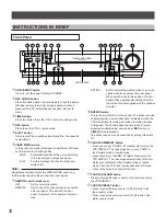
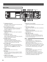
Front Panel

+

TIMER

ON

/

STANDBY

PICTURE

SOFT

SHARP

EJECT

VIDEO MODE

TAPE REMAIN

TIME LAPSE VIDEO

4Head 960Hour

DISPLAY

PLAY

STOP

REV

FWD

TIME MODE

SET

SHIFT

TRACKING

LOCATION SELECT

COUNTER

ALARM

RESET

MEMORY

AUTO

B/W

REMOTE

OFF REMOTE OPTION

BUZZER

ON       OFF

REC

REC CHECK

PAUSE/STILL

2

3

4

1

5

6

7

9

10 11

8

12

13

14

19

21

22

16

18

15

17

20

23

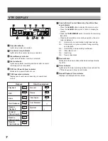
VTR DISPLAY

1

ON/STANDBY button
Press to turn the power ON and STANDBY.

2

REC CHECK button
Press this button while in record mode to check the picture
that was just recorded. After an approximate 2 second
playback the VTR automatically goes back into record
mode.

3

TIMER button
Press this button to set the VTR in timer recording mode.

4

REC button
Press to set the VTR in record mode.

5

EJECT button
Press to eject the cassette automatically from the cassette
compartment.

6

VIDEO MODE switch
In the event of a weak color signal or insufficient S/N ratio,
set this switch to the B/W position.

AUTO

: Automatically switches the circuit according

to the input signal or playback signal.

B / W

: Forcibly switches the circuit to black and

white mode.

Note:

Regardless of what position the VIDEO MODE switch is in,
the EE output signal is the same as the input signal.

7

REMOTE switch (mode lock)
OFF

: Set for normal operation.

REMOTE : Set for use with optional module connected

onto rear panel. This will lock the front
panel. Set switch to this position for mode
lock.

OPTION

: Set for external operations when you use an

option module connected onto rear panel.
When switch is set to this position, the front
panel will be operationally limited. (See the
Instruction Manual supplied with the optional
module.)

8

BUZZER switch
This is the on/off switch for the buzzer. The buzzer sounds
continually when dew condensation is detected, when the
VTR starts alarm recording, and when recording reaches
to tape end. The buzzer beeps five times with a record-
protected cassette being inserted when REC button or
TIMER button is pressed.
The buzzer sound may be cancelled by setting this switch
off.

9

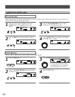
COUNTER MEMORY button
• Press once to set “COUNT. M” (counter memory) on the

VTR DISPLAY. The tape stops at a count of “0000” in
fast-forward mode or rewind mode.

• Press twice to set “ALARM. M” (alarm memory) on the

VTR DISPLAY. The tape stops automatically at the first
alarm event detected in fast-forward mode or rewind
mode. Then the VTR is set to playback after still mode.

• Press three times to cancel this function.

p

COUNTER ALARM button
Press to display the tape counter or the alarm counter on
the VTR DISPLAY.

q

COUNTER RESET button
• Press to reset the tape counter to “0000” while in the

tape counter mode.

• Press to reset the alarm counter to “A-00” while in the

alarm counter mode.

Summary of Contents for ADR8045X

Page 1: ...r DISPLAY PLAY STOP REV FWD TIME MODE SET SHIFT TRACKING LOCATION SELECT COUNTER ALARM RESET MEMORY PAUSE STILL ENGLISH FRAN AIS DEUTSCH Instruction Manual Mode d emploi Bedienungsanleitung TIME LAPSE...

Page 2: ...correct the interference at his own expense In the spaces provided below record the Model and Serial No located at the rear of your video cassette recorder Model No Serial No Retain this information...

Page 3: ...o virtual real time record in A18 mode See page 19 Internal time date generator This VTR includes an internal time date generator necessary for documentation purposes See page 13 On screen programming...

Page 4: ...ut signal 7 REMOTE switch mode lock OFF Set for normal operation REMOTE Set for use with optional module connected onto rear panel This will lock the front panel Set switch to this position for mode l...

Page 5: ...u on the screen u LOCATION SELECT button Press to change the position of superimposed characters on the screen i TRACKING buttons Adjust to eliminate noise from playback picture o PLAY button Press to...

Page 6: ...nel 1 TAPE END OUT terminal Signal output terminal to annunciate to other devices that the tape has run out on the VTR 2 REC TRIGGER OUT terminal Signal output terminal to control the switching interv...

Page 7: ...Battery Temperature For charging 0 C to 80 C For operating 20 C to 80 C For storing 30 C to 80 C Charging time more than 48 hours Notes Use only for this VTR Do not dispose of the batteries into fire...

Page 8: ...AY PLAY PLAY PLAY PLAY PLAY PLAY 7 Counter Alarm Counter Remaining Tape Error Mes sage indicator Press the ALARM button to display the alarm counter Press the ALARM button again to return to display t...

Page 9: ...PLAY button the time mode can be selected Each time pressing the REW button during still playback mode the Reverse Field Advance playback one field will be carried out 3 STOP button Press to stop tape...

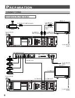
Page 10: ...THROUGH IN ON 75 FRONT PANEL DISABLE ENABLE REMOTE FUSE 1A 125V AC IN 1 2 3 4 VIDEO INPUT VIDEO OUTPUT EXT REF INPUT To QUAD OUT To VIDEO IN To VIDEO OUT To VIDEO IN To AC OUTLET 230V Quadrant picture...

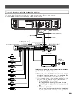
Page 11: ...C IN IN GND RESET OUT GND OUT GND TAPE END ALARM REC TRIGG IN OUT VIDEO IN OUT AUDIO SEE MANUAL SEE MANUAL IN ONE SHOT When using the VTR connected to a frame sequential switcher pay attention to the...

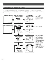
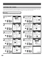
Page 12: ...l screen MENU Screen normal screen M E N U CLOCK SET SETUP SETUP DISPLAY MODE END DISPLAY TIME DATE SEARCH M E N U CLOCK ADJUST SETUP DISPLAY MODE END DISPLAY PROGRAM ALARM RECALL TIME DATE SEARCH RES...

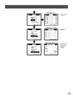
Page 13: ...GRAM Screen Setting of timer recording M E N U CLOCK ADJUST SETUP SETUP DISPLAY MODE END DISPLAY PROGRAM ALARM RECALL TIME DATE SEARCH 1ST AL6 AL5 AL4 AL3 AL7 ALARM RECALL AL1 MENU DISPLAY AL2 ALARM R...

Page 14: ...utton to return to the normal screen CLOCK SET MENU DISPLAY DAY MONTH YEAR 28 1 95 TUE 1 00 TIME DAYLIGHT SAVING TIME IN CLOCK SET MENU DISPLAY DAY MONTH YEAR 28 8 95 MON 1 00 TIME DAYLIGHT SAVING TIM...

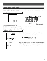
Page 15: ...ime Playback or Recording time display On Screen Position Press the LOCATION SELECT button to adjust the display to desirable position The display moves in the direction shown by the arrows 17 30 02 A...

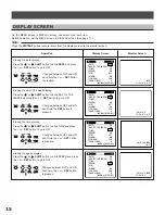
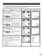
Page 16: ...SET button to go to OFF Changes between OFF and ON each time the or SET button is pressed Erasing the speed display Press the or SHIFT button to blink SPEED and press the or SET button to go to OFF Ch...

Page 17: ...ISPLAY DATE ON MENU DISPLAY DAY OF THE WEEK ON CHAR LINES 6 17 30 02 A 3 V01 28 8 96 WED VTR number TIME ON SPEED ON VTR OFF ALARM ON 12H 24H 24H DISPLAY DATE ON MENU DISPLAY DAY OF THE WEEK ON CHAR L...

Page 18: ...pressed 3 Press the COUNTER MEMORY button to make COUNT M Counter Memory to light Alarm Memory When you want to view the location where alarm recording was performed 1 Press the STOP button 2 Press t...

Page 19: ...faster Note It is possible to compute the remaining time for E 180 tape The display will not be correct for other kinds of tape Error Message When an abnormality occurs during operation the error code...

Page 20: ...ape used Audio recording is possible in the A3 A12 A18 and A24 hour modes The A12 A24 48 72 120 168 240 480 720 and 960 modes are time lapse modes For one shot recording set the VTR in the L01 L02 or...

Page 21: ...button Safety Tab A video cassette is equipped with a safety tab to prevent accidental erasure When the tab is removed recording is not possible Cassette indicator Adhesive tape If you wish to record...

Page 22: ...op mode to protect the video tape and heads Repeat recording restart recording alarm recording etc also operate during recording When recording is interrupted or the recording time is changed the pict...

Page 23: ...the or SHIFT button to blink SETUP and press the or SET button 3 Press the or SHIFT button to blink RESTART REC 4 Press the or SET button to go to ON M E N U CLOCK ADJUST SETUP SETUP DISPLAY MODE END...

Page 24: ...ON 120H SU1 ON 120H SA2 ON 120H SA1 ON 120H DLY ON 120H PROGRAM FR1 ON 120H MENU DISPLAY FR2 ON 120H Friday 1 2 Saturday 1 2 Sunday 1 2 Daily 1 Press the DISPLAY button The MENU screen appears on the...

Page 25: ...timer recording press the POWER button or the TIMER button The time difference between start time and end time should be more than 1 minute If they are same timer recording doesn t work The accuracy o...

Page 26: ...TU1 ON 120H TH1 ON 120H PROGRAM MO1 ON 8 15 120H MENU DISPLAY MO2 ON 120H M E N U CLOCK ADJUST SETUP SETUP DISPLAY MODE END DISPLAY PROGRAM ALARM RECALL TIME DATE SEARCH TH2 ON 120H WE2 ON 120H WE1 O...

Page 27: ...ton to set to SKIP if you don t need daily timer recording SU2 ON 120H SU1 ON 9 00 17 00 A24H SA2 ON 120H SA1 ON 9 00 17 00 A24H DLY ON 8 30 17 00 A18H PROGRAM FR1 ON 8 00 19 00 A12H MENU DISPLAY FR2...

Page 28: ...he VTR can be programmed to record in the following time modes during alarm recording A3 A12 A18 A24 ALARM RECORDING Recording Recording pause Stop Recording Recording pause Stop Alarm input Alarm Rec...

Page 29: ...output for power source to any of external devices To GND To alarm out Warning External interface Alarm lamp or alarm buzzer To alarm in Alarm switch Connecting alarm reset input To GND To alarm rese...

Page 30: ...N U CLOCK ADJUST SETUP DISPLAY MODE END DISPLAY PROGRAM ALARM RECALL TIME DATE SEARCH RESTART REC OFF TAPE END MODE STOP ALARM STOP S E T U P 1SHOT REC FIELD 1F MENU DISPLAY INTERVAL 0 2S ALARM REC TI...

Page 31: ...DISPLAY TIME MODE SET SHIFT TRACKING LOCATION SELECT Operation of One shot Recording 1 Press the TIME MODE button to select L01 L02 or L03 2 Press the DISPLAY button 3 Press the SHIFT button to make...

Page 32: ...ccepted during recording pause Each time pressing the SET button the display changes as follows 0 2s 0 5s 1 0s 2 0s Each time pressing the SET button the display changes in the reverse order 1SHOT REC...

Page 33: ...DE END DISPLAY PROGRAM ALARM RECALL TIME DATE SEARCH M E N U CLOCK ADJUST SETUP DISPLAY MODE END DISPLAY PROGRAM ALARM RECALL TIME DATE SEARCH RESTART REC OFF TAPE END MODE STOP ALARM STOP S E T U P 1...

Page 34: ...R to Auto Rewind even if an alarm condi tion occurred then set TAPE END ALARM to CONT in the MENU SCREEN M E N U CLOCK ADJUST SETUP SETUP DISPLAY MODE END DISPLAY PROGRAM ALARM RECALL TIME DATE SEARCH...

Page 35: ...o recording mode at beginning of the tape Caution If you need the VTR to repeat record even if an alarm condi tion occurred then set TAPE END ALARM to CONT in the MENU SCREEN Now the Repeat Recording...

Page 36: ...d recording for A18hours 0 06 s camera D 0 06 s camera C 0 06 s camera B 0 06 s camera A A B C D A B C D Video track Vertical synchronization Each time a video track is recorded the video camera is au...

Page 37: ...STOP S E T U P 1SHOT REC FIELD 1F MENU DISPLAY INTERVAL 0 2S ALARM REC TIME 15S SPEED A 3H Change to SETUP Screen 1 Each time the SET button is pressed the display changes as follows FIXED PULSE DISPL...

Page 38: ...r modes pay attention to the following points The picture may be somewhat horizontally unstable however this is not a malfunction of the VTR The upper section of the picture on the monitor screen may...

Page 39: ...SHUTTLE Dial You can also activate the picture search and slow playback of various speed by turning the shuttle dial on the VTR SHUTTLE dial STOP 2nd Step 2nd Step CENTER 1st Step 1st Step n o i t c e...

Page 40: ...till playback continues for ten minutes the VTR auto matically returns to playback Field Advance Playback Used when you want to analyze a scene in more details during playback Turn the SHUTTLE dial to...

Page 41: ...DAY 28 MENU DISPLAY HOUR 17 FORWARD MINUTE 30 REVERSE TIME DATE SEARCH DAY 28 MENU DISPLAY HOUR 17 FORWARD MINUTE 30 REVERSE TIME DATE SEARCH DAY 28 MENU DISPLAY HOUR 17 DISPLAY TIME MODE SET SHIFT T...

Page 42: ...FWD REV FWD REV FWD Notes In the cases shown below Alarm Memory search may be not carried out If the alarm recording is not carried out for more than those listed in the following chart then the alar...

Page 43: ...GND DC5V 200 ms or greater Ground input 0V 0 5V Open IN 100 10K 10K 10K 10K 0 001 GND DC5V 220 TAPE END GND 220 OUT GND DC5V 2 2K 220 10 OUT GND DC5V DC5V RESET 100 10K 10K 10K 10K 0 001 GND 200 ms or...

Page 44: ...MODE button to go to the A3 hour mode 7 Is the playback picture normal Is there anything abnormal about the recorded date and time 8 Press the REC button 9 Check the playback picture recorded in A3 ho...

Page 45: ...nsult your dealer DISPLAY TIME MODE SET SHIFT TRACKING LOCATION SELECT 2 Press the SHIFT button to blink SETUP and press the SET button M E N U CLOCK ADJUST SETUP SETUP DISPLAY MODE END DISPLAY PROGRA...

Page 46: ...STOP REV FWD TIME MODE SET SHIFT TRACKING LOCATION SELECT COUNTER ALARM RESET MEMORY PAUSE STILL DEW H SP What is condensation If you pour cold beer in a glass water droplets gather on the surface of...

Page 47: ...pe been inserted Is the REMOTE switch OFF Is the Dew lamp blinking The VTR is not operating because the safety functions are operat ing Wait until the blinking stops with the Power switch ON Has the V...

Page 48: ...rculation to prevent internal heat build up Do not place the VTR on soft surfaces rugs blankets etc too near materials such as curtains and draperies or in a built in installation such as a bookcase o...

Page 49: ...ignal Horizontal resolution 330 lines monochrome mode 260 lines color mode in A3 mode Video S N More than 43 dB in A3 mode color mode Audio input Line input 308mV rms more than 47k pin jack Microphone...

Page 50: ...49 INTRODUCTION ENGLISH PREPARATION RECORDING OPERATION PLAYBACK OPERATION NOTICE MEMO...

Page 51: ......

Page 52: ...each FL 33442 Phone 800 241 6678 Fax 954 420 4498 American Dynamics 10 Corporate Drive Orangeburg N Y 10962 Phone 914 365 1000 Tech Support Center 800 442 2225 Fax 914 365 3273 CamEra U S Corporate He...

Reviews: