


select either
(normal) or
(split color) mode. Once the mode
has been changed, press the
ENTER BUTTON (13)
to continue the setup
functions or after 8 seconds to automatically return to the main menu. To
return to the main menu without making any adjustments press the
MENU
BUTTON (10)
again.
Pan Inversion
Tap the
MENU BUTTON (10)
until
is shown on the display.
Pressing the
ENTER BUTTON (13)
will cause the display to blink and allow
the pan function to be changed. Use the
DOWN (11)
and
UP (12)
buttons
to select either
(normal) or
(pan inversion) mode. Once the
mode has been changed, press the
ENTER BUTTON (13)
to continue the
setup functions or after 8 seconds to automatically return to the main menu.
To return to the main menu without making any changes, press the
MENU
BUTTON (10)
again.
Tilt Inversion
Tap the
MENU BUTTON (10)
until
is shown on the display.
Pressing the
ENTER BUTTON (13)
will cause the display to blink and allow
the tilt function to be changed. Use the
DOWN (11)
and
UP (12)
buttons
to select either
(normal) or
(tilt inversion) mode. Once the
mode has been changed, press the
ENTER BUTTON (13)
to continue the
setup functions or after 8 seconds to automatically return to the main menu.
To return to the main menu without making any changes, press the
MENU
BUTTON (10)
again.
Display Inversion -
This function will flip the display read out by
180.˚ Inverting the display will allows it to be read when the unit is hung from
the ceiling.
Tap the
MENU BUTTON (10)
until
is blinking on the display.
Pressing the
ENTER BUTTON (13)
will cause the display to blink and allow
the display mode to be changed. Use the
ENTER
button to change to the
mode
(display inversion), It will automatically store after 8 seconds.
Or press the
ENTER
button again to return to
(display normal). To
return to the main menu without making any adjustments press the
MENU
BUTTON (10)
again.
Display normal mode for the fixture putting on the floor.
Display inversion mode for the fixture fixing under ceiling.
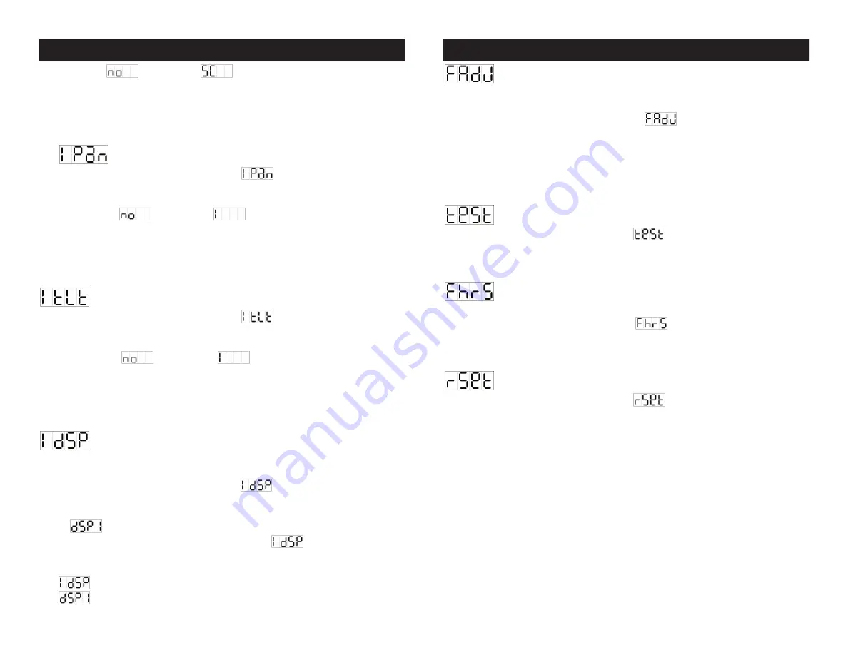
Focus Adjust -
This turns the light on and holds the head steady
at different angles, so the unit can easily be focused. Also use this function to
optimize the lamp (see lamp optimization on page 20).
Tap the
MENU BUTTON (10)
until
is blinking in the display.
Tapping on
ENTER BUTTON (13)
will move the head to different angles and
hold it steady. With each tap of the
ENTER BUTTON (13)
the pan angles will
change and tilt will hold steady at 90˚. The available pan angles are as fol-
lows; 0°, 90°, 180°, and 270°. To return to the main menu press the
MENU
BUTTON (10)
.
Self-Test -
This function activates the units internal test mode.
Tap the
MENU BUTTON (10)
until
is blinking in the display. Tap
ENTER BUTTON (13)
and the unit will run the built-in self-test program. To
return to the main menu press the
MENU BUTTON (10)
.
Fixture Hours -
The function tracks the unit’s operating hours.
Use this function to track the usage hours on the lamp.
Tap the
MENU BUTTON (10)
until
is blinking in the display. Tap
ENTER BUTTON (13)
and the display will detail the unit’s working hours. To
return to the main menu press the
MENU BUTTON (10)
.
Reset -
This function resets the unit to the default settings.
Tap the
MENU BUTTON (10)
until
is blinking in the display. Tap
ENTER BUTTON (13)
and the reset process will begin. The reset function
can take up to 60 seconds. To return to the main menu press the
MENU
BUTTON (10)
.
Auto Spot 150™
System Menu
Auto Spot 150™
System Menu
©
American DJ
®
- www.americandj.com - Auto Spot 150™ Instruction Manual Page 16
©
American DJ
®
- www.americandj.com - Auto Spot 150™ Instruction Manual Page 15


