background image

 1 

Introduction

REhub enables adding Solar PV to existing back up solutions that use UPS/Inverter and Batteries.
REhub controls the charging of the batteries from from two sources – the Grid (charging by the

existing UPS/Inverter) and the installed Solar PV. 

REhub

 provides the right combination for adding

Solar PV. REhub  

intelligently controls

  the charging process in a way that keeps the  

batteries

safe

 and therefore extends their life. They allow the 

maximal use of Solar

 power.

 2 

REhub MPPT Eco Operation 

 2.1 

REhub Operation 

REhub prioritizes keeping the Batteries charged for sufficient back up. There are two sources of

energy to deliver power to the batteries. Solar PV panels and the Grid  Mains through the back up
Inverter.REhub   extracts   power   from   the   Solar   Panel   using   a  

high   efficiency   MPPT   based

charger

. MPPT stands for Maximum Power Point tracking and the unit extracts power from the

Solar panels at the Voltage and Current that delivers the maximum power (called the Maximum

Power Point). Since this Maximum Power Voltage and Current Varies, the Unit uses sophisticated
algorithms   to   'Track'   this   maximum   power   point.   Additionally,   REhub   allows   the   conversion   of

existing Inverters to Solar based systems. REhub does this by controlling the Mains Input to the
Inverter. At all times, REhub ensures that the batteries are kept absolutely safe and maximum

Solar power is used to power the Loads. REhub is designed to work with Inverters (12V or 24V) of
any make. However it is advisable to use REhub with efficient, Pure Sine Wave output Inverters. 

Determine  the  approximate   Loads  (day   time  Load   connected   to  the   Inverters)   and  match  the
amount of Solar panels installed so that the energy generated per day is approximately equal to

the energy consumed by the loads for best results with your Solar addition. 
REhub functions in the following manner:

When Batteries are discharged – the batteries are charged using both the Solar PV and Grid
if Mains power is available.

When Batteries are >90% charged (Voltage >13.5/27V for at least 5 minutes) AND Solar PV
is available, the GRID based charging from UPS Inverter is cut off, Energy for the Loads and

Charging the batteries is supplied from Solar PV. 

When the Battery Voltage drops below 12.3/24.6V and remains in this state for at least 5
minutes OR Solar PV is unavailable, the Mains Input to the Inverter is switched on again.

The set points can be changed using a special cable 'Amberlink'.The configuration using Amberlink
is given in a separate manual available with Amberlink. 

 2.2 

Battery charging stages

REhub follows a three stage charging from the Solar PV. 

Bulk mode : As much current as available and permissible for the batteries is delivered to
the batteries

Float mode : Only as much current as need to keep the batteries charged completely is
delivered.

Absorb Mode : The unit keeps the battery Voltage constant till the Current absorbed by the
battery is lesser than 1A. 

 3 

General information

 3.1 

About this User Manual

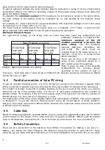
This manual contains all the necessary information and procedures to install, configure, use and

troubleshoot REhub Solar MPPT chargers for use with Inverters. It does not contain  information

3       


  V3.0

User Manual`

Summary of Contents for Rehub MPPT Eco-12

Page 1: ...e Warranty Period And Terms PLEASE PRESERVE THIS DOCUMENT Scan for storing contact information in your phone http amberroot com blog category video Copyright Amberroot Systems Pvt Ltd 2020 All rights reserved Amberroot Systems Private Limited 251 252 3rd Main 3rd Cross Road JP Nagar 3rd Phase Bangalore 560078 Contact 917899396778 info amberroot com www amberroot com ...

Page 2: ...ng from handling use or treatment that are not explicitly mentioned in this manual In particular damages arising from the following causes are excluded from the warranty 1 Voltage higher than 90V across PV or battery terminals 2 Battery cables connected across PV input terminals 3 Accidental presence of liquids in the equipment or oxidation due to condensation 4 Damage resulting from falls or mech...

Page 3: ...to use REhub with efficient Pure Sine Wave output Inverters Determine the approximate Loads day time Load connected to the Inverters and match the amount of Solar panels installed so that the energy generated per day is approximately equal to the energy consumed by the loads for best results with your Solar addition REhub functions in the following manner When Batteries are discharged the batterie...

Page 4: ...MENT IS NEITHER DESIGNED NOR GUARANTEED TO SUPPLY INSTALLATIONS USED FOR VITAL MEDICAL CARE NOR ANY OTHER CRITICAL INSTALLATION ENTAILING POTENTIAL RISKS OF DAMAGE TO PEOPLE OR TO THE ENVIRONMENT We assume no responsibility for the infringement of patent rights or other third parties rights resulting from the use of the Charger Amberroot reserves the right to make any modifications to the product ...

Page 5: ... Description Comment 1 Terminal to connect Solar Ve Ensure appropriate cable size is used and ends properly crimped to avoid accidental shorts from stray strands Ensure that the input Voltage and Current String sizing do not exceed name plate ratings 2 Terminal to connect Solar Ve 3 Terminal to connect Battery Ve 4 Terminal to connect Battery Ve 5 3 PIN 15 A Plug to connect AC input from Mains Con...

Page 6: ...PV string To get the required charging power 2 or more strings are usually to be connected in parallel Each string connected in parallel must be composed by the same number of modules of the same type The number of strings connected in parallel depends on the Isc of each string When you need to determine the Isc of the parallel array it is the Isc of each panel multiplied by the number of parallel...

Page 7: ...t a Voltage approximately equal to the open circuit voltage of the array Note if the installation is being done in the night you will not get the Voc value but likely to get a Voltage which is much lesser C Complete the Battery GND to Inverter connections and the AC live from Mains connection Switch on the AC MCB Put the Inverter to normal mode Take care not to Swap Solar PV and Battery connection...

Page 8: ...f the batteries is below a set value As a user you can decide to OVERRIDE the decision of REhub by forcing REhub to keep the Mains switch ON In ONAlwas For On Always mode REhub keeps the Mains ON at all times In ON1Day for ON One Day mode REhub keeps REhub ON for the next 24 Hours and goes back automatically to Auto Mode at the end of 24 Hours In OFF Grid mode REhub continues to keep the Mains inp...

Page 9: ...t Trip Reduce PV Capacity Wait Internal Error due to transients arising due to long battery cables Error in System Prot Trip Batt Prot Trip Reduce battery Cable length Wait Internal Error due to transients arising due to insufficient wire gauge Error in System Prot Trip Connect proper gauge wire Over temperature The unit cycles through Charging and Tripping Error in System High Temperature Wait fo...

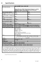
Page 10: ...ar Charger to enable addition of Solar PV to existing home inverters Maximizes the usage of Solar Recommended Solar module STC Wp Output Current Continuous Max PV Open Circuit Voltage VOC Power Conversion Efficiency typical Ports 1PV Ve input 1PV Ve input 1Battery Ve Input 1Battery Ve 1 15A and 6A 3 Pin Socket 1 6A 1 Meter long wire with 3 Pin Plug 1 Mode Switch 1 Modbus port 16 X2 Backlit charact...

Page 11: ...b screens shows that the battery system voltage is detected connect the AC 3 Pin plug to Mains supply Your REhub installation is complete Close the L plate once the system working is verified on the display screen WAIT till you see REhub switching off the MAINS input to the Inverter and the Inverter indicates that it is in back up mode Sl no Description Desired Valve Measured value Verified 01 Che...

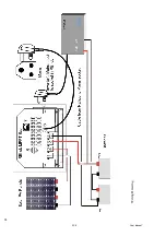
Page 12: ...12 V3 0 User Manual Wiring Drawing ...

Reviews: