Structure and function
Catros-2TX BAG0159.8 02.20
57
Harrow system 12-250 Hi For rollers: DUW580
Spring-mounted clearing system 167 For roller: UW580
Spring blade system 142 For roller: WW580
Page 1: ...os 8003 2TX Catros 8003 2TX Catros 9003 2TX Catros 9003 2TX Mounted compact disc harrow MG5527 BAG0159 8 02 20 Printed in Germany Please read and follow this operating manual before putting the machine into operation Keep it in a safe place for future use en ...
Page 2: ...y itself The person in question would not only harm himself but also make the mistake of blaming the machine for pos sible failures instead of himself In order to ensure success one should enter the mind of a thing make himself familiar with every part of the ma chine and get acquainted with how it s handled Only in this way could you be satisfied both with the machine and with yourself This goal ...
Page 3: ...r s address AMAZONEN WERKE H DREYER GmbH Co KG Postfach 51 D 49202 Phone E mail Hasbergen 49 5405 501 0 amazone amazone de Spare part orders Spare parts lists are freely accessible in the spare parts portal at www amazone de Please send orders to your AMAZONE dealer Formalities of the operating manual Document number MG5527 Compilation date 02 20 Copyright AMAZONEN WERKE H DREYER GmbH Co KG 2020 A...
Page 4: ...uctions before putting the machine into operation Only after careful reading will you be able to benefit from the full scope of your newly purchased machine Please ensure that all the machine operators have read this operating manual before they put the machine into operation Should you have any questions or problems please consult this op erating manual or contact your local service partner Regul...
Page 5: ...served 22 2 15 Safety conscious working 22 2 16 Safety information for users 23 2 16 1 General safety and accident prevention information 23 2 16 2 Hydraulic system 26 2 16 3 Electrical system 27 2 16 4 Attached machines 27 2 16 5 Brake system 28 2 16 6 Tyres 29 2 16 7 Cleaning maintenance and repairs 29 3 Loading and unloading 30 4 Product description 31 4 1 Overview of subassemblies 31 4 2 Safet...
Page 6: ...he total tractor weight tractor axle loads and load capacities as well as the minimum ballast 68 6 1 2 Requirements for tractor operation with attached machines 72 6 2 Securing the tractor machine against unintentional start up and rolling 76 7 Coupling and uncoupling the machine 77 7 1 Coupling the machine 77 7 2 Uncoupling the machine 80 8 Adjustments 82 8 1 Aligning the implement horizontally 8...
Page 7: ...oller 110 12 7 Check the coupling device 111 12 8 Tyres wheels 112 12 8 1 Tyreinflation pressure 112 12 8 2 Mounting tyres workshop work 113 12 9 Replacing discs workshop work 113 12 10 Aligning the disc gangs relative to each other 114 12 11 Replacing or turning the cutters of the cutting roller 114 12 12 Hydraulic system 115 12 12 1 Labelling hydraulic hose lines 116 12 12 2 Maintenance interval...
Page 8: ...pecified in the operating manual are always viewed in the direction of travel 1 3 Diagrams used Instructions for action and reactions Tasks to be carried out by the user are presented as numbered in structions Always keep to the order of the instructions The reaction to instructions is given by an arrow Example 1 Instruction for action 1 Reaction of the machine to instruction for action 1 2 Instru...
Page 9: ...te To replace damaged warning pictograms If you still have queries please contact the manufacturer Obligations of the user Before starting work anyone charged with working with on the ma chine is obliged To comply with the basic workplace safety instructions and acci dent prevention regulations To read and understand the section General safety information of this operating manual To read the secti...
Page 10: ...e shall be available to the operator at the latest on the comple tion of the contract Guarantee and liability claims for damage to peo ple or goods will be excluded if they can be traced back to one or more of the following causes Improper use of the machine Improper installation commissioning operation and mainte nance of the machine Operation of the machine with defective safety equipment or imp...
Page 11: ...mme diate death or serious physical injury WARNING Indicates a medium risk which could result in death or serious physical injury if not avoided If the instructions are not followed then this may result in death or serious physical injury CAUTION Indicates a low risk which could incur minor or medium level physical injury or damage to property if not avoided IMPORTANT Indicates an obligation to sp...
Page 12: ...arly 2 4 Safety and protection equipment Before each commissioning of the machine all the safety and protec tion equipment must be properly attached and fully functional Check all the safety and protection equipment regularly Faulty safety equipment Faulty or disassembled safety and protection equipment can lead to dangerous situations 2 5 Informal safety measures As well as all the safety informa...
Page 13: ...Instructed persons are those who have been instructed in their assigned tasks and in the possible risks in the case of improper behaviour have been trained if necessary and have been in formed about the necessary protective equipment and measures 3 People with specialist technical training shall be considered as a specialist Due to their specialist training and their knowledge of the appropriate r...
Page 14: ...ement work Regularly check that bolted connections are firmly secured and tight en if necessary When the maintenance work is completed check the function of the safety devices 2 10 Constructive changes You may make no changes expansions or modifications to the ma chine without the authorisation of AMAZONEN WERKE This is also valid when welding support parts Any expansion or modification work shall...
Page 15: ...d spare parts from third parties there is no guarantee that they have been designed and manufactured in such a way as to meet the requirements placed on them AMAZONEN WERKE accepts no liability for damage arising from the use of unapproved spare parts wear parts or auxiliary materials 2 11 Cleaning and disposal Handle and dispose of any materials used carefully in particular When carrying out work...
Page 16: ... 16 Catros 2TX BAG0159 8 02 20 2 13 Warning pictograms and other signs on the machine 2 13 1 Positioning of warning pictograms and other labels The following diagrams show the arrangement of the warning picto grams on the machine ...
Page 17: ...s Field 1 is a pictogram describing the danger surrounded by triangular safety symbol Field 2 is a pictogram showing how to avoid the danger Warning pictograms explanation The column Order number and explanation provides an explanation of the neighbouring warning pictogram The description of the warning pictograms is always the same and specifies in the following order 1 A description of the dange...
Page 18: ...s the tractor engine is running Ensure that all other persons also keep a sufficient safety distance from the danger area of the machine as long as the tractor engine is running MD082 Danger of falling from treads and platforms when riding on the machine This danger will cause serious injuries anywhere on the body or death It is forbidden to ride on the machine and or climb the running machine Thi...
Page 19: ...220 kV over 220 up to 380 kV 1 m 2 m 3 m 4 m MD095 Read and understand the operating manual safe ty information before starting up the machine MD096 Danger of infection to the whole body from liquids escaping at a high pressure hydraulic fluid This danger will cause serious injuries over the whole body if hydraulic fluid escaping at high pressure passes through the skin and into the body Never att...
Page 20: ...e information in the rele vant sections of the operating manual MD 114 This pictogram indicates a lubrication point MD 154 Risk of injury due to non compliance with the approved transport width Before folding the implement install the transport safety bar MD 155 This icon designates the restraint points for tieing the machine to a transport vehicle allowing the machine to be transported in a safe ...
Page 21: ...ctor and attached machine This danger can cause extremely serious and potentially fatal injuries Do not remain in the danger area between tractor and machine while the tractor engine is running and the tractor is not secured against unintentional rolling Instruct anyone in the danger area between tractor and machine to leave the danger ar ea while the tractor engine is running and the tractor is n...
Page 22: ...gh non secured working areas Failure of important machine functions Failure of prescribed methods of maintenance and repair Danger to people through mechanical and chemical impacts Risk to environment through leakage of hydraulic fluid 2 15 Safety conscious working Besides the safety information in this operating manual the national general workplace safety and accident prevention regulations are ...
Page 23: ...ions the driving characteristics of the tractor and the connected machine Connecting and disconnecting the machine Only connect and transport the machine with tractors suitable for the task When connecting machines to the tractor three point hydraulic system the attachment categories of the tractor and the ma chine must always be the same Connect the machine to the prescribed equipment in accordan...
Page 24: ... work ensure that you understand all the equip ment and actuation elements of the machine and their function There is no time for this when the machine is already in opera tion Do not wear loose fitting clothing Loose clothing increases the risk over being caught by drive shafts Only start up the machine when all the safety equipment has been attached and is in the safety position Comply with the ...
Page 25: ...cribed brake delay for the loaded vehicle combination tractor plus connected machine Check the brake power before moving off When turning corners with the machine connected take the broad load and balance weight of the machine into account Before moving off ensure sufficient side locking of the tractor lower links when the machine is fixed to the three point hydrau lic system or lower links of the...
Page 26: ...brake ο Take out the ignition key Have the hydraulic hose line checked at least once a year by a specialist for proper functioning Replace the hydraulic hose line if it is damaged or worn Only use AMAZONE original hydraulic hose lines The hydraulic hose lines should not be used for longer than six years including any storage time of maximum two years Even with proper storage and approved use hoses...
Page 27: ...of retrofitting of electrical units and or compo nents on the machine with a connection to the on board power supply the user must check whether the installation might cause faults on the vehicle electronics or other com ponents ο Ensure that the retrofitted electrical and electronic compo nents comply with the EMC directive 2004 108 EC in the appropriate version and carry the CE label 2 16 4 Atta...
Page 28: ...g rings on the hose couplings of the supply and brake line Only move off with the machine connected when the pressure gauge on the tractor shows 5 0 bar Drain the air reservoir every day Before driving without the machine lock the hose couplings on the tractor Hang the hose couplings of the machine supply and brake lines in the appropriate empty couplings When filling up or replacing the brake flu...
Page 29: ...ntenance and repair work on the machine when ο the drive is switched off ο the tractor engine is at a standstill ο the ignition key has been removed ο the connector to the machine has been disconnected from the on board computer Regularly check the nuts and bolts for a firm seat and retighten them as necessary If the machine or parts of the machine are raised secure them against unintentional lowe...
Page 30: ...r for loading and unloading as long as the tractor fulfils the power re quirements Compressed air brake system You may only move off with the machine connected if the pres sure gauge on the tractor shows 5 0 bar If the machine is to be loaded onto or unloaded from a transport vehi cle it must be coupled to a suitable tractor Loading A person to help with manoeuvring is required for loading Secure ...
Page 31: ...The machine is composed of the following main components Hydraulically foldable frame Two row concave disc arrangement Trailing roller Swinging chassis 4 1 Overview of subassemblies Machine in working position 1 Draw rail 2 1 st row of discs 3 2nd row of discs 4 Roller The middle part of the roller can be de signed to be hydraulically folded or rigid 5 Crushboard 6 Swinging chassis 7 Foldable mach...
Page 32: ...st unintentional unfolding of the im plement ο No ContourFrame via hydraulic valve ο ContourFrame via locking hook 4 3 Supply lines Safety and protection equipment Hydraulic hose lines Electric cable for lighting Connection to hydraulic brake or dual circuit pneumatic braking system ο Brake line with coupling head yellow ο Supply line with coupling head red ...
Page 33: ...hts turn indicators 2 Warning signs square 3 Red reflectors 4 Number plate holder 5 Labelling of the max permissible speed 6 Side Reflectors 1 2 limiting lights 2 2 warning signs Side reflectors each left and right side not illustrated Connect the lighting system to the 7 pin tractor socket via the pin ...
Page 34: ... 3 0 MPa Slopes can be travelled Along the contours Direction of travel to left 15 Direction of travel to right 15 Along the gradient Up the slope 15 Down the slope 15 The intended use also includes Compliance with all the instructions in this operating manual Execution of inspection and maintenance work Exclusive use of AMAZONE original spare parts Other uses to those specified above are forbidde...
Page 35: ... special safety regulations of the appropriate section shall be valid No one may stand in the machine danger area as long as the tractor engine is running with a connected PTO shaft hydraulic system as long as the tractor and machine are not protected against unintentional start up and running The operating person may only move the machine or switch or drive the tools from the transport position t...
Page 36: ...rmissible total weight 5 Technically permissible drawbar load A0 6 Technically permissible axle load A1 Machine rating plate The machine rating plate specifies 1 Vehicle ID no 2 Machine ID no 3 Product 4 Basic weight kg 5 Perm drawbar load kg 6 Perm rear axle load kg 7 Perm system pressure bar 8 Perm total weight kg 9 Factory 10 Model year CE marking CE label with specification of the year of manu...
Page 37: ...middle roller 4000 mm for rigid middle roller Transport height 3450 mm 3950 mm 4000 mm Transport length 8650 mm Working speed 12 18 km h Discs smooth serrated Disc diameter 510 mm 510 mm 510 mm Disc spacing 250 mm 250 mm 250 mm No of discs 56 mm 64 mm 72 mm Working depth 50 140 mm Tyre pressure Running gear tyre 550 45 22 5 LI159A8 tyre 700 40 22 5 LI160A8 2 7 bar Support wheel 2 5 bar ...
Page 38: ...load index on the tyre indicates the load capacity of the tyre The speed index on the tyre indicates the maximum speed at which the tyre has the tyre load capacity according to the load index The tyre load capacity is only achieved when the tyre inflation pressure matches the nominal pressure Load index 140 141 142 143 144 145 146 147 Tyre load capacity kg 2500 2575 2650 2725 2800 2900 3000 3075 L...
Page 39: ...ssure is lower than the nominal pressure the tyre load capacity is reduced In that case observe the reduced payload of the implement Please also follow the specifications of the tyre manufacturer WARNING Danger of accident In event of too low inflation pressure the stability of the vehicle is no longer guaranteed ...
Page 40: ...hydraulic fluid circuits of all standard tractor brands Control units Depending on equipment see page 42 Service brake system Dual circuit service brake sys tem 1 hose coupling red for the supply line 1 hose coupling yellow for the brake line Hydraulic braking system 1 hydraulic coupling in accordance with ISO 5676 The hydraulic braking system is not allowed in Germany and several other EU countri...
Page 41: ...ndividual components 5 1 Function The Catros compact disc cultivator is suitable for shallow stubble cultivation directly after threshing seed bed preparation in spring for maize or sugar beet incorporation of catch crops e g yellow mustard The two row disc arrangement ensures soil cultivation and rotavation The trailing wedge ring roller serves to re consolidate the soil ...
Page 42: ...he tractor control unit must be used in different types of activa tion depending on the hydraulic function Latched for a permanent oil circulation Tentative activate until the action is executed Float position free oil flow in the control unit Marking Function Tractor control unit Yellow Machine Move into working position readjust the sections pres sure Double acting Move into headlands posi tion ...
Page 43: ...en coupling the hydraulic hose lines observe the coloured mark ings on the hydraulic plugs Check the compatibility of the hydraulic fluids before connecting the machine to the hydraulic system of the tractor Do not mix any mineral oils with biological oils Observe the maximum approved hydraulic fluid pressure of 210 bar Only couple clean hydraulic connectors Push the hydraulic plug s into the hydr...
Page 44: ...hose lines 1 Swivel the actuation lever on the control valve on the tractor to float position neutral position 2 Unlock the hydraulic connectors from the hydraulic sockets 3 Protect the hydraulic connectors and hydraulic connector sock ets against soiling with the dust protection caps ...
Page 45: ...k when the supply line red is connected to the tractor Be fore connection of the supply line red the machine must there fore be connected to the tractor s lower links and the tractor s handbrake must be applied The wheel chocks must also not be removed until the machine is connected to the tractor s lower links and the tractor s handbrake is applied To activate the dual circuit pneumatic braking s...
Page 46: ...st fol lowed by the hose coupling of the supply line red The operating brake of the machine moves out of the brake position immediately the red hose coupling has been coupled 1 Open the tractor coupling head caps 2 Remove brake line coupling head yellow from the idle coupling 3 Check coupling head seals for damage and cleanness 4 Clean dirty seals replace damaged seals 5 Fasten the brake line coup...
Page 47: ... been uncoupled Always keep to this order as otherwise the service brake system will trip and may set the unbraked machine moving When the machine is uncoupled or pulled away from the trailer air is vented from the trailer brake valve supply line The trailer brake valve is automatically switched and operates the service braking system independently of the automatic load dependent braking force reg...
Page 48: ... 1 Remove the protective caps 2 If necessary clean the hydraulic connector and hydraulic socket 3 Connect the hydraulic socket on the ma chine face with the hydraulic connector on the tractor face 4 Tighten the hydraulic screw union hand tight if present 5 4 2 Uncoupling the hydraulic service brake system 1 Release the hydraulic screw union if present 2 Protect the hydraulic connectors and hydraul...
Page 49: ...c brake connected Pressure accumulator of the emergency brake is being charged DANGER Risk of accident through brake malfunction After withdrawing the safety splint e g when activating the emergen cy brake it is essential to insert the safety splint into the brake valve from the same side Otherwise the brake will not function After reinserting the safety splint carry out a brake test for the servi...
Page 50: ...is operated by turning the crank which in turn operates the spindle and bowden cable A Apply the tractor parking brake B Release parking brake Correct the setting of the parking brake if the spindle s tension is no longer sufficient Ensure that the bowden cable is not lying or rubbing against other vehicle parts When the parking brake is off the bowden cable must be slightly slack ...
Page 51: ...c rubber sprung suspension of the individual discs enables adaptation to soil unevenness evasion by the discs when hard obstacles are encountered e g stones This protects the individual discs against damage The working depth can be adjusted hydraulically with display on a scale manually using the threaded spindle The alignment of the disc gangs to one another can be adjusted using threaded spindle...
Page 52: ...ce with the maximum authorised transport height of 4 m 1 Side disc 2 Depth adjustment 3 Pin for locking the transport and working position 5 8 Crushboard optional The crushboard serves to level and crumble the soil It is located between the discs and the roller In front of the discs The working intensity can be adjusted mechanically or hydraulically 1 Crushboard at the front 2 Crushboard at the re...
Page 53: ...essure and it chops up plant resi dues When it is taken out of service the cutting roller is lifted and secured by a stop tap 1 Individual hydraulically activated segments 2 If cutters are worn reverse the cutters 3 Hydraulic preloading 4 Hydraulic accumulator 5 Pressure control valve 6 Pressure gauge for preload pressure 7 Stop tap ...
Page 54: ... holes Provides very good crumbling Cage roller SW600 The cage roller can be used where lighter reconsolidation of the soil is required Disposes of a very good self propulsion Wedge ring roller KW580 with adjustable scraper Very well suited for medium soils Wedge ring roller KWM 650 with Matrix profile and adjustable scraper Very well suited for light medium and heavy soils Angle profile roller WW...
Page 55: ...uble U profile roller DUW580 Very well suited for light and medium soils Resistant to clogging and good load bearing capacity Disc roller DW600 Very well suited for light medium and heavy soils Provides very good crumbling Resistant to clogging and sticking offers a good load bearing capacity Double Disc roller DDW Very well suited for light medium and heavy soils Resistant to clogging and stickin...
Page 56: ...ing and can swing freely to the front 2 Position of the positioning pin to lock the exact following harrow during road transport 3 Install the road safety bar for road transport 4 Depending on the harrow system adjust the harrow height so that it is free of play Make the same adjustments on all of the setting points Raise and peg the harrow to take it out of operation Attach the transport safety b...
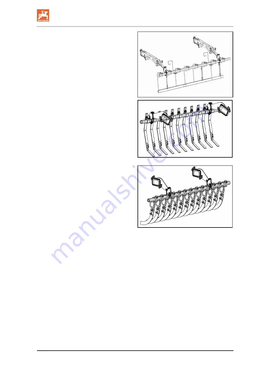
Page 57: ...Structure and function Catros 2TX BAG0159 8 02 20 57 Harrow system 12 250 Hi For rollers DUW580 Spring mounted clearing system 167 For roller UW580 Spring blade system 142 For roller WW580 ...
Page 58: ...following functions are implemented by this measure Lift implement in front in headlands position Hydraulic float position as working position Relieving of hydraulic lines for decoupling Lower and lift drawbar separately for coupling 1 Spacer elements for locking the transport position of the drawbar and to align the implement behind the tractor 2 Hydraulic cylinder drawbar adjustment 3 Stop valve...
Page 59: ...TX BAG0159 8 02 20 59 5 13 1 Hydraulic drawbar control Working position Working position transport position Lift lower drawbar for coupling and decoupling Lock drawbar and running gear depressurise the hydraulic system for decoupling ...
Page 60: ... pressure observe the pressure gauge is greater than the value for the correct pre load pressure During operation the blue tractor control unit is operated in float position and the hydraulic load ing is active Correct pre load pressure 60 bar is set as soon as the blue control unit is in float position Pressure reservoir with pressure gauge pres sure reservoir and adjustable pressure relief valve...
Page 61: ...c securing with locking pin Bring the jack into the desired position 1 Pull the hand lever to release the locking mechanism When lowering the jack falls down Quickly let go of the hand lever 2 Swing the jack to the end position 3 Ensure that the locking pin is engaged in place 5 16 Support wheels The support wheels stabilise the implement under uneven ground conditions prevents oscillations and th...
Page 62: ...specific regulations implements are equipped with a safety chain The safety chain must be mounted at a suitable point on the tractor as prescribed before travelling 5 18 Safety device against unauthorised use Lockable device for the drawbar eye ball brack et or lower link crosspiece prevents unauthor ised use of the machine ...
Page 63: ...er on the support wheel for determination of the worked area The counter shows the distance run in the work ing position in kilometres Trailing of the feeler wheel and driving back wards distort the area calculation The counter also continues counting when driv ing backwards Area ha 0 1 x displayed value km x working width m ...
Page 64: ...rease nipple for filling the tank 1 Rotary knob blue pause time standard 2 hours 2 Rotary knob red lubrication time standard 6 minutes 3 Button for starting the lubrication cycle 4 Sealing cap Set the rotary knob according to the table Do not set the rotary knob to 0 Pause times Rotary knob blue 1 2 3 4 5 6 7 8 9 A B C D E F Hours 1 2 3 4 5 6 7 8 9 10 11 12 13 14 15 Lubrication times Rotary knob r...
Page 65: ...e pump must match with the arrow on the hopper 5 21 GreenDrill catch crop sowing unit The GreenDrill catch crop sowing unit enables the sowing of fine seeds and catch crops during soil cultivation with the Catros disc cultivator 1 GreenDrill 2 Foldable ascent 3 Locking pin for securing the foldable ascent See also the GreenDrill operating manual Fold the access ladder to the transport position bef...
Page 66: ...ure equipment makes it possible to mounted approved liquid manure spreaders manufactured by Vogelsang on the implement The liquid manure equipment includes Left right distributor 2 liquid manure pump brackets Spreading tube with bracket for mounting in front of the first disc gang Hose connection ...
Page 67: ...tractor which is suitable for the task The tractor and machine must meet the national road traffic regulations The operator and the user shall be responsible for compliance with the statutory road traffic regulations WARNING Risk of contusions cutting catching drawing in and knocks in the area of hydraulically or electrically actuated components Do not block the operator controls on the tractor wh...
Page 68: ...the tractor must always be subjected to at least 20 of the empty weight of the tractor The tractor must achieve the brake delay specified by the tractor manufacturer even with the machine connected 6 1 1 Calculating the actual values for the total tractor weight tractor axle loads and load capacities as well as the minimum ballast The approved total tractor weight specified in the vehicle document...
Page 69: ...ee technical data of tractor and front ma chine mounting or front weight or measure ment a1 m Distance from the centre of the front axle to the centre of the lower link connection See tractor operating manual or measure ment a2 m Distance between the centre of the lower link connection point and the centre of gravi ty of the front machine mount or front weight centre of gravity distance See techni...
Page 70: ... the tractor operating manual in the table Section 6 1 1 7 6 1 1 4 Calculation of the actual total weight of the combined tractor and machine H L V tat F T G G Enter the numeric value for the calculated actual total weight and the approved total tractor weight specified in the tractor operating manual in the table Section 6 1 1 7 6 1 1 5 Calculation of the actual rear axle load of the tractor TH t...
Page 71: ...ity and insufficient tractor steering and brake power It is forbidden to couple the machine to the tractor used as the basis for calculation if One of the actual calculated values is greater than the approved value There is no front weight if required attached to the tractor for the minimum front ballast GV min Ballast your tractor with weights at the front or rear if the tractor axle load is exce...
Page 72: ...actor possess sufficient permissible support capability for the supported weight ac tually present ο that the axle loads and weights of the tractor altered by the drawbar load are within the approved limits If necessary weigh them ο that the tractor s actual static rear axle weight does not ex ceed the permissible rear axle weight ο that the permissible total weight of the tractor is observed ο th...
Page 73: ... coupling Ø 80 mm ISO 24347 Lower hitch Towing hooks hitch hooks ISO 6489 19 Drawbar eye Centre bore Ø 50 mm Eyelet Ø 30 mm ISO 5692 1 Swivel drawbar eye compatible only with form Y hole Ø 50 mm ISO 5692 3 Drawbar eye Centre bore Ø 50 mm Eyelet Ø 30 41 mm ISO 20019 Drawbar Category 2 ISO 6489 3 Drawbar eye Centre bore Ø 50 mm Eyelet Ø 30 mm ISO 5692 1 Socket Ø 40 mm ISO 5692 2 Ø 40 mm ISO 8755 Ø 5...
Page 74: ...device of the implement Drawbar of the implement Coupling device of the tractor The actual DC value calculated for the combination must be less than or equal to the DC values specified The permissible DC values of the implement can be found on the rating plate of the coupling de vice 1 and the drawbar 2 The permissible DC value of the tractor coupling device can be found directly on the coupling d...
Page 75: ...actual DC value of a combination to be coupled is calculated as follows DC g x T x C T C Fig 2 T permissible total weight of your tractor in t See tractor operat ing manual or vehicle documentation C axle load of the implement t loaded with the permissible mass without drawbar load working load g Gravity 9 81 m s ...
Page 76: ...ated ο as long as the tractor engine is running with the PTO shaft hydraulic system connected ο if the ignition key is in the tractor and the tractor engine can be started unintentionally with the PTO shaft hydraulic system connected ο if the tractor and machine have not each been prevented from unintentionally rolling away by applying their parking brakes and or securing them with wheel chocks ο ...
Page 77: ...the machine Only actuate the operator controls for the tractor s three point hydrau lic system only from the intended workstation only if you are outside of the danger area between the tractor and the machine 7 1 Coupling the machine WARNING Danger of breaking during operation insufficient stability and insufficient tractor steering and braking power on improper use of the tractor You may only con...
Page 78: ...roper way ο When coupling the machine to the tractor s three point hy draulic system ensure that the attachment categories of the tractor and the machine are the same WARNING Risk of power supply failure between the tractor and the ma chine through damaged supply lines During coupling check the course of the power lines The power lines must give slightly without tension bending or rubbing on all m...
Page 79: ...to the tractor before coupling the implement to the tractor 3 1 Drive the tractor up to the implement in such a manner that a free space approx 25 cm remains between tractor and implement 3 2 Secure the tractor against unintentional starting and rolling away 3 3 Couple supply lines to the tractor 3 4 Position the lower link hooks so that they are aligned with the lower pivot points on the implemen...
Page 80: ...r in reverse to the implement so that the coupling device can be coupled 4 Place the control valve on the drawbar in the posi tion 5 Actuate the tractor control unit yellow Lower drawbar 6 Couple the coupling device 7 Bring the control valve on the drawbar into position 8 Lift the stand into transport position 9 Remove wheel chocks 10 Release the parking brake 7 2 Uncoupling the machine WARNING Ri...
Page 81: ...t yellow to float position and depressurise the hydraulic hose lines 3 7 Uncouple the supply lines Uncouple the implement with ball bracket 1 Safeguard tractor and implement against rolling off unintention ally See page 76 2 Lower the stand 3 Decouple the implement from the tractor 3 1 Decouple the coupling device 3 2 Place the control valve on the drawbar in the position 3 3 Actuate the tractor c...
Page 82: ... of the tractor machine combination Secure the tractor and the machine against unintentional start up and rolling before making adjustments to the machine See Page 76 8 1 Aligning the implement horizontally The implement is aligned horizontally by 1 supporting the retracted drawbar cylinder on the spacer ele ments 2 adjusting the spindle on the support wheels The implement only needs to be aligned...
Page 83: ...cesses must completely enclose the pis ton rod 5 Remount the pin and secure it with the linch pin Aligning the sections using the support wheels The sections are aligned horizontally by adjust ing the spindle length on the support wheel Adjust the same spindle length on both support wheels Adjusting the spindle using the ratchet 1 Remove the linch pin 3 2 Engage the turning lever 2 in the required...
Page 84: ...ual working depth adjustment WARNING Risk of falling off the implement Do not climb onto the implement parts Set the working depth evenly using 2 spindles in the centre and 2 spindles in the outer area of the implement 1 Actuate yellow tractor control unit Lift implement into headlands position 2 Switch the yellow tractor control unit to float position Lower the front part of the implement for bet...
Page 85: ...pin 3 2 Engage the turning lever 2 in the required direction 3 Use the hand lever 1 to lengthen or short en the spindle 4 Secure the adjustment using the linch pin 3 5 Rest the hand lever in parking position on the frame and secure with a linch pin The scale 4 serves for orientation during ad justment ...
Page 86: ...ust ed see page 97 Manual adjustment 1 Secure the tractor against unintentional starting and unintentional rolling away 2 Adjust the intensity using the crank and secure with the linch pin Turning the crank towards the right lower intensity Turning the crank towards the left higher intensity The display shows the set intensity A high displayed value indicates high intensity 1 Scale 2 Read off edge...
Page 87: ...Re tighten the lock nut Factory setting 25 bar Setting range 25 35 bar Maximum preload pressure 60 bar Higher preload pressure can result in dam age 8 5 Working depth of the side elements The adjustment is performed on the raised side elements using the 2 slots on the left and right sides of the implement 1 Secure the tractor against unintentional starting and unintentional rolling away 2 Loosen t...
Page 88: ...r the scraper 3 Adjust the scraper in the slot 4 Tighten the bolt again Wedge ring roller Do not adjust the distance between scraper and spacer ring to less than 10 mm to avoid excessive wear Tooth packer roller Adjust the distance between the scraper and shaft between 0 5 to 4 mm 8 7 Height of towing eye With the machine removed the height of the towing eye 1 can be adjusted to the tractor Releas...
Page 89: ...isual check that the upper and lower link pins are secured with a lynch pin against unintentional re lease WARNING Risk of contusions cutting catching drawing in and knocks when making interventions in the machine through unintentional machine movements On folding machines check that the transport locks are locked correctly Secure the machine against unintentional movements before starting transpo...
Page 90: ...with the maximum load of the connected machine and the approved axle and support loads of the tractor If necessary drive only with a partially filled hopper WARNING Risk of falling from the machine if riding against regulations It is forbidden to ride on the machine and or climb the running ma chine Rear harrow optional WARNING Risk of injury due to unprotected pointed ends of the harrow Before fo...
Page 91: ...ays have full control over the tractor with the attached machine In so doing take your personal abilities into account as well as the road traffic visibility and weather conditions the driving characteris tics of the driver and the connected machine WARNING Risk of being crushed cut caught drawn in or struck if the ma chine is unintentionally released from its attached or hitched position Each tim...
Page 92: ...nlock the safeguard that protects against undesired unfolding and simultaneously 3 Actuate blue tractor control unit Unfold the implement Actuate the tractor control unit a little longer until the section pressure has been reached through the pre load pressure ContourFrame After unfolding actuate the tractor control unit until the pressure gauge displays the correct pre load pressure 60 bar If the...
Page 93: ...t yellow Raise the implement completely 2 Set the smallest working depth This ensures compliance with the authorised transport width 3 Reduce the spindle length of the support wheels to 550 mm This ensures compliance with the authorised transport width 4 Put the side elements into transport position 5 Swivel in and secure the spacer elements on the drawbar cylin der 6 Rear harrow optional Before f...
Page 94: ...ement swivelled up into transport position Left side element swivelled to the side into transport position 1 Pull out the bolt 2 Both border elements can be folded into transport position can be unfolded into working position 3 Fix the transport position with the pin and secure using a linch pin WARNING Crushing hazard for hands Be particularly careful when folding the border elements 10 1 4 Lifti...
Page 95: ...elling in the spacer elements the recesses must complete ly enclose the piston rod Attaching removing the spacer elements on the drawbar cylin der 1 Actuate yellow tractor control unit Completely lift out the implement 2 Pull out the bolt 3 Transport position swivel in the spacer elements on the drawbar cylinder or Operating position swivel the spacer elements away from the drawbar cylinder Always...
Page 96: ...he set value 10 2 1 Using the cutting roller 1 Align the implement horizontally If the implement is working too deep at the front the cutting roller can be damaged 2 Open the stop tap of the preload device 3 Actuate the beige tractor control unit Lower the cutting roller and build up preload tension 4 Switch the beige tractor control unit to the float position 10 3 Driving on the headlands Before ...
Page 97: ...he same length If this is not the case the hydraulic cylinders can be synchronised 1 Keep actuating the green tractor control unit until the hydraulic cylinders are completely extended 2 Continue actuating the control unit for another 10 s An overflow process is initiated that flushes all of the cylinders This adjusts the cylinders to the same length This procedure should also be performed before ...
Page 98: ...bination Secure the tractor and machine against unintentional starting and unintentional rolling away before you perform any cleaning servicing or maintenance work on the machine See page 76 WARNING Risk of contusions cutting catching drawing in and knocks through unprotected danger points Mount protective equipment which you removed when cleaning maintaining and repairing the machine Replace defe...
Page 99: ...r the handling and removal of cleaning agents Cleaning with a high pressure cleaner steam jet Always observe the following points when using a high pressure cleaner steam jet for cleaning ο Do not clean any electrical components ο Do not clean any chromed components ο Never aim the cleaning jet from the nozzle of the high pres sure cleaner steam jet directly on lubrication and bearing points ο Alw...
Page 100: ...mpletely and replace it with new grease Lubricants For lubrication work use a lithium saponified multipurpose grease with EP additives Company Lubricant name ARAL Aralub HL2 FINA Marson L2 ESSO Beacon 2 SHELL Retinax A 12 2 1 Lubrication point overview Designation Quantity Lubrication intervall h 1 Draw rail 1 50 2 2 10 3 Draw bar 1 50 4 1 50 5 Boom 2 50 6 Support wheel 2 50 7 Section hydraulic cy...
Page 101: ...Cleaning maintenance and repairs Catros 2TX BAG0159 8 02 20 101 ...
Page 102: ...hole implement Visual inspection before opera tion Brake system Drain 109 Weekly every 50 working hours Component Servicing work see page Workshop work Hydraulic system Inspection for defects 115 X Wheels Chec k the air pressure Wheel nut check 112 Brake system Perform visual inspection 94 Coupling device Check for damage deformation and cracks 111 Every three months 200 operating hours Component ...
Page 103: ...Component Servicing work See page Workshop work Brake system Check the brake drum for dirt 105 X Automatic slack adjuster Functional check Settings 106 X Every 2 years Component Servicing work See page Workshop work Axle running gear support wheel Checking the hub bearing 93 X As required Component Servicing work see page Workshop work Scraper Adjust 88 Upper lower link pin Replace 106 Disc Check ...
Page 104: ...list personnel Special care is required for welding torch cutting and drill ing work in the vicinity of brake lines Always carry out a braking test after any adjusting or repair work on the braking system General visual inspection WARNING Carry out a general visual inspection of the brake system Ob serve and check the following criteria Pipe lines hose lines and coupler heads must not be exter nal...
Page 105: ...e wheel and brake drum must be removed Checking the play on wheel hub bearings 1 To check the play on wheel hub bearings raise the axle until the 2 wheels turn freely 3 Place a lever between the tyre and the ground and check the play If bearing play can be detected Adjust the bearing play 1 Remove the dust cup or hub cap 2 Remove the split pin from the axle nut 3 Tighten the wheel nut while turnin...
Page 106: ...cylinder pressure rod is max 35 mm the wheel brake must be readjusted The setting is carried out on the hexagonal ad justing screw of the slack adjuster Set the free travel a to 10 12 of the connected brake lever length B e g lever length 150 mm free travel 15 18 mm Checking the function of the automatic slack adjuster 1 Secure the machine against rolling away and release the service brake and par...
Page 107: ... direction by the ring until no more water es capes from the compressed air tank 4 If the escaping water is dirty let off air un screw the drainage valve from the com pressed air tank and clean the compressed air tank The compressed air tank must not move around in the tensioning belts be damaged show any outward signs of corrosion dam age The rating plate must not show signs of corrosion be loose...
Page 108: ...d remove the bolts 1 2 Unscrew the bolts 2 by a few turns 3 Lift the plate 3 over the rubber seal 4 and turn to the side The unit is under spring tension 4 Remove the rubber seal 5 Clean and grease the sealing surfaces O ring and filter Replace the rubber seal if necessary Correctly position the O ring on the plastic ring 6 Reassemble in the reverse sequence Bolt tightening torque 1 2 5 Nm Bolt ti...
Page 109: ... more than 0 15 bar after 10 minutes 6 Seal any leaking areas or replace leaking valves 2 Check pressure in the air reservoir 1 Connect a pressure gauge to the test connection on the air res ervoir Set value 6 0 to 8 1 0 2 bar 3 Check brake cylinder pressure 1 Connect a pressure gauge to the test connection on the brake cylinder Set value with brake not applied 0 0 bar 4 Visual inspection of brake...
Page 110: ... for which the system has been opened bleed the brake system because air may have entered the pressure hoses 1 Slightly loosen the vent valve 2 Actuate the tractor brake 3 Close the vent valve as soon as oil es capes Collect the escaping oil 4 Perform a brake check 12 5 Axle bolts 1 Axle bolts with clamping plates Check the bolts for tightness 12 6 Checking the roller Check the alignment of the bo...
Page 111: ...mension Fixing bolts Number Tightening torque Lower link trav erse Cat 3 34 5 mm Cat 4 48 0 mm Cat 5 56 0 mm M20 8 8 8 410 Nm Ball coupling K80 LI009 82 mm M16 10 9 8 300 Nm K80 LI040 82 mm M20 10 9 8 560 Nm K80 LI015 82 mm M20 10 9 12 560 Nm Drawbar eye D35 LI038 42 mm M16 12 9 6 340 Nm D40 LI017 41 5 mm M16 10 9 6 300 Nm D40 LI006 42 5 mm M20 8 8 8 395 Nm D46 LI034 48 mm M20 10 9 12 550 Nm D50 L...
Page 112: ...alists using suitable assembly tools Tyre fitting requires sufficient skills and proper assembly tools Use the jack only at the jacking points indicated 12 8 1 Tyreinflation pressure Inflate the tyres with the indicated nominal pressure The value for the nominal pressure can be read on the rim The value for the nominal pressure can be obtained from the tyre manufacturer Check tyre pressures regula...
Page 113: ... rims when the vehicle is in operation When fitting new tyres always use new valves for tubeless tyres or new inner tubes Always fit the valves with valve caps which have a gasket insert 12 9 Replacing discs workshop work Replace if minimum diameter 360mm The discs are replaced with the machine folded out the discs raised the machine secured against unintentional lowering To replace the discs rele...
Page 114: ... each other using the spindles Adjust both spindles for a disc segment together 1 Align the unfolded implement horizontally 2 Set the working depth to the smallest value The discs are not standing on the ground 3 Secure the tractor against unintentional starting and unintentional rolling away 4 Loosen the lock nut and adjust the spindle length retighten the lock nut Adjust the spindles to the same...
Page 115: ... the trailer Ensure that the hydraulic hose lines are connected correctly Regularly check all the hydraulic hose lines and couplings for damage and impurities Have the hydraulic hose line checked at least once a year by a specialist for proper functioning Replace the hydraulic hose line if it is damaged or worn Only use AMAZONE original hydraulic hose lines The hydraulic hose lines should not be u...
Page 116: ...Replace any worn or damaged hydraulic hose lines immediately 12 12 3 Inspection criteria for hydraulic hose lines For your own safety comply with the following inspection criteria Replace hydraulic hose lines on determining any of the follow ing during the inspection Damage to the outer layer up to the ply e g scouring points cuts cracks Brittleness of the outer layer crack formation of the hose m...
Page 117: ...he hydraulic hose lines are avoided Use appropriate arrangements and fixing to prevent any scouring of the hoses on components or on each other If necessary secure hydraulic hose lines using protective co vers Cover sharp edged components ο The approved bending radii may not be exceeded When connecting a hydraulic hose line to moving parts the hose length must be appropriate so that the smallest a...
Page 118: ...Hydraulics diagram 118 Catros 2TX BAG0159 8 02 20 13 Hydraulics diagram Catros Catros 7003 2TX 8003 2TX ...
Page 119: ...Hydraulics diagram Catros 2TX BAG0159 8 02 20 119 Catros Catros 9003 2TX ...
Page 120: ...Hydraulics diagram 120 Catros 2TX BAG0159 8 02 20 Working depth of discs Crushboard ...
Page 121: ... 315 380 M 18 27 290 405 485 M 18x1 5 325 460 550 M 20 30 410 580 690 M 20x1 5 460 640 770 M 22 32 550 780 930 M 22x1 5 610 860 1050 M 24 36 710 1000 1200 M 24x2 780 1100 1300 M 27 41 1050 1500 1800 M 27x2 1150 1600 1950 M 30 46 1450 2000 2400 M 30x2 1600 2250 2700 M M4 M5 M6 M8 M10 M12 M14 M16 M18 M20 M22 M24 2 4 4 9 8 4 20 6 40 7 70 5 112 174 242 342 470 589 Coated screws have different tighteni...
Page 122: ......