background image

12

   6.  When drum is fully engaged with the surface, gradually adjust your pace for adequate finish removal.  Keep sander in motion while 


the  drum is engaged with the surface or dwell marks will occur.

    7.  Move the machine in the direction of the grain in the wood whenever it is possible.  Sand the surface at a constant pace.

    8.  Gradually feather-cut out at the termination point by easing the drum up with the control lever. (See Figure 13) 

    9.  Repeat technique described in steps 5, 6, 7, and 8 and sand back down pass just made.  When completed, begin a new pass by overlapping 


previous pass half the width of the abrasive. Stagger termination points to prevent a distinct ridge and to promote a better blend when edging.

    10.   Empty contents of the dust bag into a metal container located outside the building.  Dust bag should be emptied whenever full, as indicated 

            on bag.


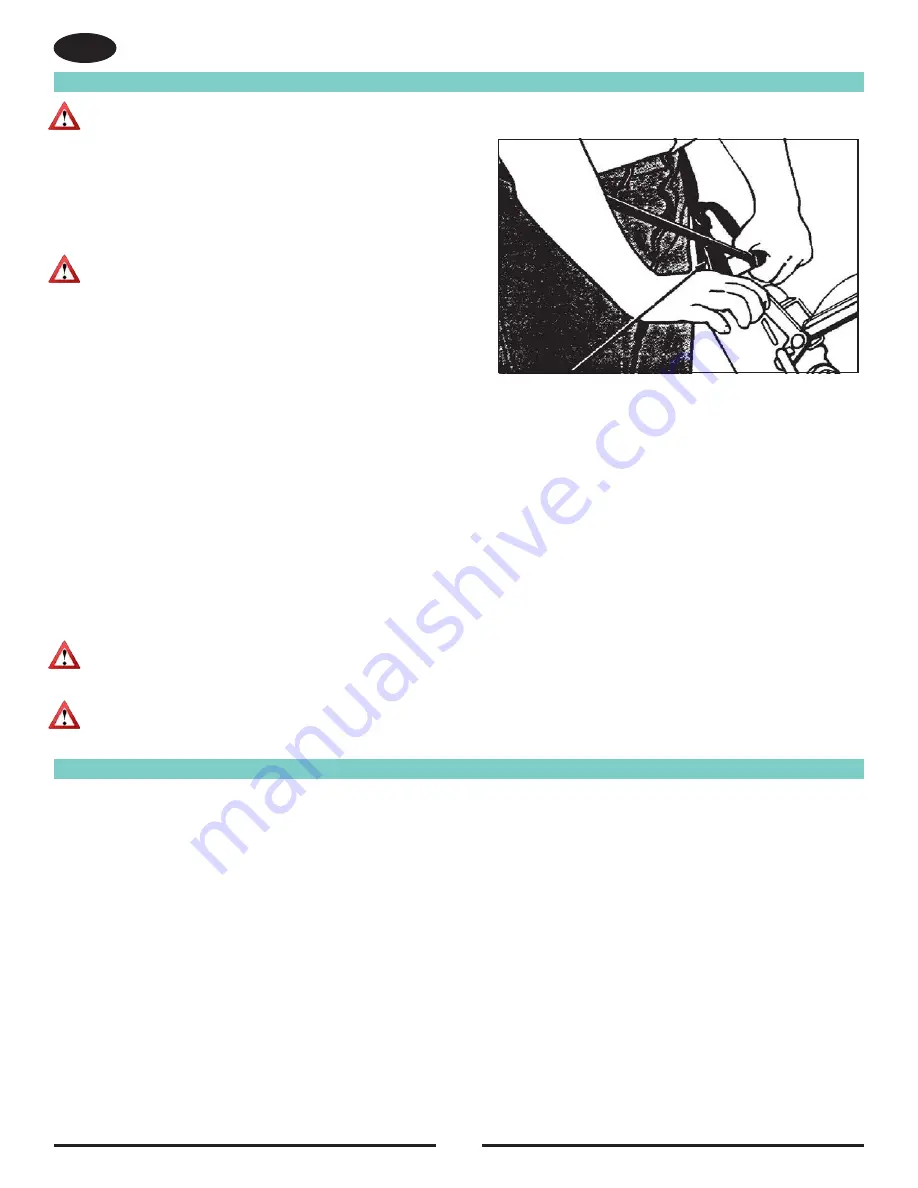
 WARNING:  Serious operator injury could occur if the operator 

has tied or strapped the loose end of the operator’s 

belt strap to the machine.  Always wrap the strap 

so that you can let go and get away quickly in case 

of bag fire or explosion.

    4.  Activate the control switch.


 CAUTION:  To prevent damage to the floor, make sure the 

machine is in motion when the drum is engaged 

with the floor.

    5.  Feather-cut in by easing the drum down onto the surface    


with the control lever while the sander is in motion. 

Operating Instructions

Figure 13

EN

WARNING: 

Do not overfill dust bag or serious fire may result.  Never leave a dust bag containing dust unattended.  


Sanding dust can self ignite and cause a fire or explosion.  Use only genuine American Sanders replacement bags.

CAUTION: 

An overfilled dust bag may effect machine balance and performance.  Do not handle or disturb dust bag and elbow 


while sanding or damage to the floor may occur.

Sanding Cuts & Sandpaper

Initial Cut

The purpose of the initial cut is to remove old finish and gross imperfections on the floor surface.  The sanding equipment should be adjusted to 

heavy sanding pressure setting and a coarse abrasive belt should be used.  If the surface is severely damaged by deep scratches, preexisting dwell 

marks, uneven planks, etc., it may be necessary to sand across or diagonally to the grain to restore evenness to the surface.  If these conditions are 

not present, the initial cut should be done in the direction of the grain.  

If glazing, loading, or burning takes place immediately into an initial cut, select a coarser abrasive.  If this should occur during an initial cut, the 

abrasive has dulled and must be replaced.  

Final Cuts

The purpose of a finishing cut is to remove the scratches produced during the initial cut.  Use a fine (60 - 80 grit) grain abrasive and a reduced 

sanding pressure setting.

If the surface remains rough after a finishing cut, it may be necessary to use an even finer grain of abrasive (80 - 100 grit).  Care should be taken in 

selecting the grit size of the abrasive.   A very fine grain will close the pores on a wood floor making admission of a stain difficult.

If glazing or burning should occur immediately into a finishing cut, reduce the sanding pressure.  If it should occur during a finishing cut, the abrasive 

has dulled and must be replaced.

Summary of Contents for American SANDERS FloorCrafter

Page 1: ...Belt Sander FloorCrafter Operator s Manual...

Page 2: ......

Page 3: ...l have it explained fully before attempting to operate this machine All directions given in this book are as seen from the operator s position at the rear of the machine This product is intended for c...

Page 4: ...of the drum Always lift the cord over the machine Do not move the machine by the power cord C Shock hazard Do not use the machine if it has been rained on or sprayed with water DANGER To avoid injury...

Page 5: ...capable of stopping flying debris generated by various operations The eye protection must be capable of stopping flying debris generated by various operations The dust mask or respirator must be capa...

Page 6: ...e 3 Do not operate a partially assembled power tool Keep all adjustments within manufacturer s specifications Keep all fasteners tight Operating a partially assembled power tool could result in injury...

Page 7: ...ion The FloorCrafter can be used on a variety of surfaces It is an ideal tool for wood flooring maintenance and restoration work 230V Electrical Connection Instructions This machine must be connected...

Page 8: ...hine off the floor ground until the dolly swings under the machine See Figure 3 2 Hold the dolly in position using your foot and allow the machine to tip back and rest on the dolly wheels See Figure 4...

Page 9: ...the motor See Figure 8 7 Straddle the motor and grasp the motor lift handle Using your legs lift the motor off the chassis and take it to the work site 8 Lift the chassis by grasping the front and rea...

Page 10: ...entry to the sanding chamber 6 Rotate the release lever forward See Figure 11 WARNING Never put yourself or let others be in a position to get injured if the machine should tip or fall while changing...

Page 11: ...enters the room This will help to avoid entanglement with the cord set and eliminate the need to move the cord set out of the way so frequently Work the area in a way that avoids interruption or termi...

Page 12: ...ining dust unattended Sanding dust can self ignite and cause a fire or explosion Use only genuine American Sanders replacement bags CAUTION An overfilled dust bag may effect machine balance and perfor...

Page 13: ...La forma m s segura para eliminar las marcas de vibraciones es realizar el acabado del piso con una lijadora giratoria horizontal tal como la lijadora 16 de Clarke Para minimizar las marcas de vibraci...

Page 14: ...hent le patin poussi re au ch s sis 3 Abaissez le patin poussi re pour r duire le d gagement 4 Soulevezle patin poussi re pour augmenter le d gagement 5 Alignez le patin poussi re au ch ssis puis serr...

Page 15: ...ra 18 AA AB AA AB uniforme Si es necesario realice los ajustes correspondientes 3 Marque la nueva ubicaci n del indicador en la unidad principal Alineaci n de la correa NOTA La correa de lijado debe c...

Page 16: ...ndition Sanding Chamber Periodically blow out the sanding chamber to prevent large accumulations of debris which could interfere with the performance of the tension roller NOTE The tension lever shoul...

Page 17: ...17 Troubleshooting EN...

Page 18: ...evention See Chatter Wave Prevention Close evenly spaced ripples page 13 page 13 Difficult to actuate tension release Debris interferes with mechanism Blow out sanding chamber lever Remove and disasse...

Page 19: ...19...

Page 20: ...__ ________________________________________________ ________________________________________________ ________________________________________________ ________________________________________________ _...

Page 21: ...21 Wiring Diagram RF081500 102120...

Page 22: ...22 Handle Assembly RF081200 111120 Handle Assembly 13 9 14 10 12 14 32 1 15 35 16 3 23 22 11 5 13 36 40 37 34 3 2 4 7 39 19 17 18 20 21 22 33 27 25 26 25 24 8 6 28 38 16...

Page 23: ...109A 1 NUT HEX ELASTIC LOCK SS 8 32 20 980982 1 WASHER 10 SAE FLAT PLTD 21 85613A 1 SCREW 8 32X7 8 PAN HD 22 85517A 10 SCREW 10 24 X 1 2 PHCR TYPE 23 23 51074A 2 CLAMP CABLE 24 80026A 1 BOLT SHOULDER...

Page 24: ...4 9 51 44 42 7 33 43 8 19 33 18 13 39 29 48 3 39 25 3 48 29 39 30 16 17 40 24 5 46 BASE ASSEMBLY 37 40 52 15 RF066100 051419 21 12 32 26 45 50 38 10 41 2 27 47 6 2 11 36 1 20 25 2 6 47 27 2 41 28 35 2...

Page 25: ...POOL 27 167312 2 RING RETAINER INTERNAL 28 193944 2 GROMMET 29 747304 2 RIETAINING RING 1 250 INTERNAL 30 920196 2 NUT 1 2 13 HEX JAM 31 920208 1 NUT 1 4 20 HEX 32 962727 2 SCREW 8 32 X 1 2 33 962823...

Page 26: ...26 Belt Tensioner Assembly BELT TENSIONER ASSY 1 2 3 4 5 6 7 8 9 10 11 12 13 14 15 16 17 18 18 19 20 21 22 23 23 24 25 26 27 28 29 30 31 32 33 34 35 36 37 38 39...

Page 27: ...ROLLER SHAFT 16 80020A 1 BOLT SHOULDER 1 4 X 1 17 80140A 2 WASHER 5MM BOWED 18 81217A 3 NUT 1 4 20 HEX ESNA 19 81303A 1 NUT 1 4 28 20 87052A 3 WASHER FLT 1 25X1 00X 020NYLON 21 747380 2 RING ROLLER RE...

Page 28: ...28 Dolly Assembly RF066200 103116 DOLLY ASSEMBLY 11 4 11 12 2 3 11 2 11 14 5 12 10 1 7 13 8 13 6 10 8 10 8...

Page 29: ...346A 1 BRACKET RIGHT MOUNTING 4 60347A 1 BRACE DOLLY 5 60348A 1 BRACKET RIGHT 6 60349A 1 BRACKET LEFT 7 80047A 4 BOLTSHOULDER 1 2DIA X 1 3 4 8 87627A 4 WASHER 875 O D BOWED 9 170883 4 WASHER LOCK 3 8...

Page 30: ...ssembly RF081100 102120 Dust Control Assembly 8 4 16 54 12 14 24 11 38 28 25 21 23 22 42 37 50 49 51 52 50 17 9 13 10 40 15 46 47 44 43 20 30 29 48 53 26 45 19 18 2 6 39 3 1 5 7 36 35 32 17 57 56 55 4...

Page 31: ...X LOCK 27 85812A 3 SCREW 5 16 18 X 7 8 HEX HD GR5 28 920196 1 NUT 1 2 13 HEX JAM 29 60397A 1 COVER DUST THROAT 30 85517A 3 SCREW 10 24 X 1 2 PHCR TYPE 23 31 10144A 1 ASSEMBLY DUST TUBE 32 920342 1 NUT...

Page 32: ...2120 17 32 32 21 16 37 30 13 8 34 7 15 14 1 6 5 11 18 12 33 10 9 4 8 2 3 19 28 23 8 29 25 25 29 22 12 26 20 35 24 Capacitor Box Assembly 15 17 16 6 26 9 24 15 7 14 21 20 23 10 14 19 5 4 18 16 17 15 27...

Page 33: ...WREINCH ALLEN 3 16 13 NB9710 4 NUT KEPS 8 32 ZINC 14 NB007400 4 BOLT PHILLIPS PAN HD 8 32 X 1 2 15 962016 9 SCR 10 24 X 1 2 RD ST MACH 16 980982 7 WASHER 10 SAE FLAT PLTD 17 980650 7 WASHER 19 X 34 X...

Page 34: ...1051A 1 Bearing Carrier 5 51052A 1 Shaft Arbor 6 51053A 1 Pulley Drum 7 51211A 1 E Ring 25 Dia 8 51223A 1 Bearing Ball 9 51224A 1 Bearing Ball 10 60376A 1 Plate Drum End 11 60389A 1 Pin Hinge 12 70236...

Page 35: ...E RING 25 DIA 8 51223A 1 BEARING BALL 9 51224A 1 BEARING BALL 10 60376A 1 PLATE DRUM END 11 60389A 1 PIN HINGE 12 70236A 1 LABEL BELT TRACKING 13 81106A 2 NUTHEX LOCK3 4 10 14 86110A 4 SCREW 3 8 16 X...

Page 36: ...Directive 2014 30 EU of 26 February 2014 Low Voltage Directive 2014 35 EU of 26 February 2014 Machinery Directive 2006 42 EC Amending Directive 95 16 EC of 17 May 2006 Restriction of the use of certai...

Page 37: ...37 07239A Serial Tag...

Page 38: ...AND CONDITIONS FOR WARRANTY REIMBURSEMENT l Order replacement part Orders will be processed and charged as normal procedure l Call American Sanders for R A number l You will need the Machine Serial N...

Page 39: ...39...

Page 40: ...NO Company 1 Eclipse Rd l PO Box 909 Sparta North Carolina 28675 l USA www pioneereclipse com www americansanders com 1 336 372 8080 1 800 367 3550 Fax 1 336 372 2913 2020 American Sanders LT085700 Fl...

Reviews: