background image

ACCESSORY INSTALLATIONS

51

Remote Thermostat High Fan Kit

Description

When a wall mounted thermostat is used, the PTAC unit will
operate in low speed only.  Following these instructions will
allow the PTAC unit to operate on high speed only. This kit
contains twenty labels, enough for ten units.

HIGH VOLTAGE
D

ISCONNECT


ALL


POWER


BEFORE

SERVICING


OR


INSTALLING


THIS


UNIT

.

M

ULTIPLE


POWER


SOURCES


MAY


BE


PRESENT

.

F

AILURE


TO


DO


SO


MAY


CAUSE


PROPERTY

DAMAGE

PERSONAL


INJURY


OR


DEATH

.

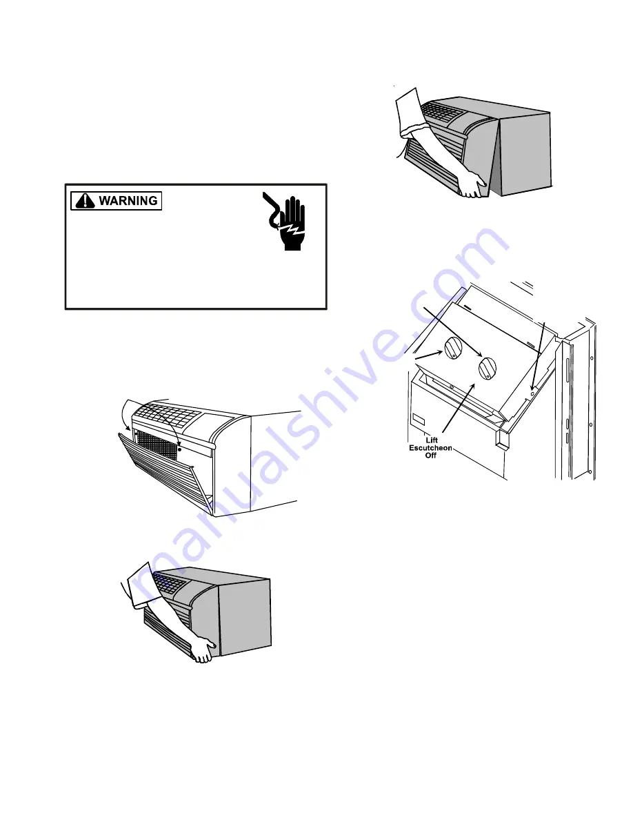
1. Remove the two screws securing the front to the chas-

sis.  

NOTE:

 Not all installations will use these screws.

Holes to 

secure front

2. Grasp the cabinet front as shown.

3. Pull the bottom of the cabinet front away from the chas-

sis until the retaining clips disengage.

4. Lift the cabinet front off the chassis.

5. Remove the unit control knobs by pulling the knobs off

the control shafts.

Pull To Remove

Mode Switch Knob

Control Panel 

Cover Screws 

Located on 

Both Sides of 
Control Panel

Pull To Remove

Thermostat Knob

6. Lifting the front edge of the escutcheon, slide the tabs at

the top of the escutcheon out of the retaining holes and
remove the escutcheon.

7. Remove the control panel cover by removing the two

screws holding the control panel cover in place.  Tilt the
control panel forward to gain access to the wiring.

IMPORTANT NOTE: 

Disconnect power to the unit and/or

turn the Master Switch on the control board to OFF when
connecting or altering wiring to any terminal - failure to do so
may result in shorting the fuse or damaging the control board.

8. On the control board switch BK16 along with all other

wires on the “FAN HIGH” and RD17 and all other wires
on the “FAN LOW” 1/4 inch terminals.

Summary of Contents for R-22

Page 1: ...sponsibility for property damage or personal injury due to improper service procedures or services performed by an unqualified person Service Instructions ACCESSORIES MANUAL R 22 Package Terminal Air Conditioners Heat Pumps is a registered trademark of Maytag Corporation or its related companies and is used under license to Goodman Company L P Houston TX All rights reserved 2001 2010 Goodman Compa...

Page 2: ...NS AND WARNINGS IN THE SERVICE MANUAL IMPORTANT NOTICES FOR CONSUMERS AND SERVICERS RECOGNIZE SAFETY SYMBOLS WORDS AND LABELS HIGH VOLTAGE DISCONNECT ALL POWER BEFORE SERVICING OR INSTALLING THIS UNIT MULTIPLE POWER SOURCES MAY BE PRESENT FAILURE TO DO SO MAY CAUSE PROPERTY DAMAGE PERSONAL INJURY OR DEATH Table of Contents When Ordering Parts 3 Circuit Breaker Kit 4 Condensate Drain Kit 6 Condensa...

Page 3: ...s Outside the U S call 1 713 861 2500 Not a technical assistance line for dealers Your telephone company will bill you for the call When Ordering Parts All product model and serial nameplates carry an additional number called the manufacturing number It is possible to have one or more like products with the samemodelnumber butthataportionofthepartswouldnotbeinterchangeable The manufacturing number...

Page 4: ...ollowing figure GE and Westinghouse use outer holes Secure one of the two small mounting clips to the mounting bracket Do not fully tighten the mounting screw at this time 2 Position the circuit breaker on the mounting bracket so that the locking tabs on the small clip installed in Step 1 hold the circuit breaker on the mounting bracket 3 Install the second small clip on the mounting bracket locki...

Page 5: ...ACCESSORY INSTALLATIONS 5 ...

Page 6: ...ng it to a drainage system will result in inadequate condensate removal possible leakage and corrosion ALGAECIDE Some algaecide products may cause dam age to the unit basepan or coils and should not be used Contact your sales representative when considering the use of a commercial algaecide Installation for Outdoor Use The drain components for outdoor use must be installed be fore the wall sleeve ...

Page 7: ...ting plate D and 1 2 drain fitting together Install the assembly into the drilled holes and secure using the two slotted mounting screws included in the kit Be sure drain tube is not restricted NOTE If the drain fitting is not connected to an indoor drainage system immediately after the wall sleeve is installed plug the hole with cork not included to pre vent indoor water damage in case it rains 4...

Page 8: ... used Contact your sales representative for the recommended algaecide pan treatment for your unit The installation and servicing of the equipment should be done by qualified experienced technicians Drain Kit Components Installation for Outdoor Use The drain components for outdoor use must be installed before the wall sleeve condenser grille 1 Remove the rear enclosure panel and the sleeve stiffene...

Page 9: ...ricted Cover the two screw heads with a good quality outdoor caulking not supplied for additional corrosion protection NOTE If the drain fitting is not connected to an indoor drainage system immediately after the wall sleeve is installed plug the hole with cork not included to prevent indoor water damage in case it rains 4 Install a 1 2 ID tube or hose not included on the drain fitting and interco...

Page 10: ...AC chassis from the wallsleeve Move the chassis where the front and back of the chassis can be easily accessed 3 Remove the discharge screen by unscrewing two screws holding the screen to the blower panel Set screen aside 4 Lift the blower panel approximately 10 inches by un screwing two screws holding the blower panel to the chassis and lift upward being careful not to pinch heater wires Condensa...

Page 11: ...inch 8 screws 12 Remove the protective adhesive backing from the plas tic U clip and mount the U clip to the plastic condenser shroud in approximately the position shown 13 Attach the p clamp to the brace with the screw pro vided see figure below 14 Place one of the hose clamps over one end of the 16 inch vinyl hose Place the same end over the barbed discharge tube of the pump assembly Place a hos...

Page 12: ...d and connect the YL5 where RD33 was connected YL3 where VT12 was connected and YL1 where BK19 was connected Connect RD33 to the piggyback terminal of YL5 VT12 to the piggyback ter minal of YL3 and BK19 to the piggyback terminal of YL1 Make sure the OR8 wire is connected from the 6 terminal of the relay to 24 volt terminal of the transformer 22 For 208 volt applications move the WH6 wire terminal ...

Page 13: ... by the original manufacturer of the package termi nal unit TO PREVENT DAMAGE TO THE UNIT DUE TO RESTRICTED AIR FLOW REMOVE ANY BAFFLES OR DEFLECTORS OF ANY KIND FROM THE OUTDOOR GRILLE CAUTION HIGH VOLTAGE DISCONNECT ALL POWER BEFORE SERVICING OR INSTALLING THIS UNIT MULTIPLE POWER SOURCES MAY BE PRESENT FAILURE TO DO SO MAY CAUSE PROPERTY DAMAGE PERSONAL INJURY OR DEATH Installation 1 Locate the...

Page 14: ... to use see note below for A series information If your unit s model number contains the letter E for the 7th digit DO NOT USE THIS KIT The correct curtain guard kit for these units is PTCB10E NOTE Use of the incorrect part may cause the guard to break and it will not be replaced by Goodman If you are in doubt about which kit is needed please contact your sales repre sentative IMPORTANT NOTE Do NO...

Page 15: ...igure 2 Figure 2 See Figures 3 and 4 for views of correctly installed curtain guard 2nd Vertical Louver 4th Vertical Louver Side Tabs attached on 2nd Horizontal Louver Tabs snapped into place Figure 3 2nd Louver 4th Louver Figure 4 View of R 22 Model with Curtain Guard Installed Correctly 3 To remove the curtain guard remove cabinet front from the chassis Rotate the cabinet front so the back of th...

Page 16: ...kit consists of a main duct for the room of origin and an extension duct to reach the adjoining room and terminal duct NOTE All required hardware is provided within kit TRANSITION BAFFLES Main Duct Kit MDK02 ExtensionDuctKit EDK02B Terminal Duct Kit TDK02B TOP 11 16 5 8 2 3 8 Ø 1 8 Ø 1 8 Hole Placement Template ...

Page 17: ... source before removing the chassis PRE ASSEMBLY Transition Front 1 If the cabinet front is screwed to the chassis remove the screw located behind the inlet grille Pull the inlet grille forward from the top of the grille to access two screws Figure 1 2 Remove cabinet front from chassis by tilting the bottom of the front forward lifting slightly up and forward FRONT MOUNTING HOLE Figure 1 Cabinet F...

Page 18: ...tition wall to drill the holes layout and drill the holes from inside the sleeve MDK ASSEMBLY Determine if the duct is to be extended to the right of the unit where controls are located or to the left of the unit oppo site the controls Figure 6 For left side extensions remove the main duct end cap and reinstall on the right end of the duct Using the four painted sheet metal screws secure the two m...

Page 19: ...W Table1 2 Place baffle on grille support brackets on main duct En sure the two extruded holes of the baffle are on top of the front bracket holes 3 Install discharge air grille on top of the air baffle Secure the grille to the duct with pal nuts provided by reaching through the opening in the bottom of the duct See figure 7 SUPPORT BRACKETS DISCHARGE AIR GRILLE AIR BAFFLE Figure 7 Air Grille Inst...

Page 20: ...be connected to the hole in the wall If necessary cut the extension duct to a length where the cut end protrudes into the wall s inner space and one inch from the adjoining room s wall surface 8 Insert the extension duct into the opening in the wall Install the extension duct by placing the slotted flange over the two screws in the main duct Using two 8 round Phillips head screws mount bottom of e...

Page 21: ...ll of the opposite room Figure 11 See wall hole dimensions illustration for sheet metal collar Figure 12 11 1 2 6 1 4 Figure 11 Wall Hole Dimension 2 Insert the sheet metal collar into the wall so that the flanges will mount flush to the wall after the collar is pushed all the way into the wall While pushing the collar into the wall make sure the extension duct is inside the collar Use four 8 scre...

Page 22: ...o gain access to the wires Power Cord 4 The incoming electrical power on all 265 volt units is fuse protected On all kits except the 5 kW kit replace the fuse with the fuse supplied with the kit On 5 kW heater kits replace the existing fuseholder with the fuseholder with fuse supplied with the kit NOTE The incoming electrical power on 230 208 volt units is not fuse protected unless a fuseholder ki...

Page 23: ...d to the fuseholder 7 Connect the power cord s green ground wire to the par tition panel using the ground screw provided in the kit 8 If the unit is mounted on a subbase with a power recep tacle remove the right front cover plate of the subbase connect the plug end of the power cord into the subbase power receptacle and route the cord up out of the sub base through the cord slot in the right side ...

Page 24: ...utdoor Section Heater Wires For single Stage Heaters Follow Step 6 then skip to Step 16 6 Connect brown 34 and brown 35 heater wires to the 1 4 inch terminals on the control board marked HEATER Single Stage Heater Schematic For two stage heaters Follow Steps 7 through 15 7 Mount the heater relay supplied with the heater kit to the middle section of the control panel Place the studs on the heater r...

Page 25: ...piggyback terminal of VT17 on the L2 terminal on the control board 13 Connect VT18 from the heater relay B terminal as shipped from the factory to the FAN HIGH terminal on the control board 14 On the LINE 2 terminal of the control board A Disconnect the power wire BK18 on 265 volt units power cord on the 230 208 volt units B Connect VT20 from the heater relay 5 terminal C Reconnect the power wire ...

Page 26: ...5 HK415E 1 5 5100 1580 6 3 7 7 15A 2 5 HK425E 2 5 8500 2580 9 9 12 3 15A 3 7 HK435E 3 7 12600 3780 14 5 18 20A 5 0 HK450E 3 5 1 5 17100 5080 19 4 24 1 25A On two stage heater kit High Heat both stages ON Low Heat stage 1 on only Recommended field supplied time delay fuses or HACR type circuit breaker 265 Volt Electric Heater and Power Cord Data LISTED ACCESSORIES PACKAGE TERMINAL AIR CONDITIONER S...

Page 27: ...ions 1 Lift the cabinet front off the chassis 2 Remove the unit control knobs by pulling the knobs off the extension shafts 3 Remove the b nut mounting the extensions to the hy dronic escutcheon COMFORT Z O N E B Nut 4 Reaching below the hydronic top remove the extensions from the chassis by pulling the extensions off the con trol shafts Pull the extensions out of the hydronic top Control Board Co...

Page 28: ...tions will use these screws Mounting Screws Location 2 Grasp the cabinet front as shown 3 Pull the bottom of the cabinet front away from the chas sis until the retaining clips disengage 4 Lift the cabinet front off the chassis 5 Remove the unit control knobs by pulling the knobs off the control shafts Pull To Remove Thermostat Knob Pull To Remove Mode Switch Knob Escutcheon 6 Lifting the front edg...

Page 29: ... CODES TYPE AND LOCATION OF FUSED DISCONNECT SWITCH ES MUST COMPLY WITH ALL APPLICABLE CODES FAILURE TO FOLLOW THESE CODES COULD RESULT IN OVERHEATING AND EQUIPMENT FAILURE Fuse Holder Kit Installation Without Subbase See page 27 for installation in a subbase C F H X X Fuseholder Fuseholder Line 1 Heater Heater Line 2 Comp Fan High Fan Low Rev Valve Electronic Board Capacitor BK 10 RD 10 Unit Elec...

Page 30: ...cation Leveling Leg Fuse Holder Knockouts Power Switch Knockout Subbase Left Side 2 Install the fuse holders using screws provided The side connector tab on the fuse holders should be towards the left 3 Connect a stripped BK 9 wire to the center of the quick connect tab of the fuse holders Wire nut the other end of this wire to the black field connection wire L2 4 Connect the other stripped BK 9 w...

Page 31: ...RS ONLY FOR ELECTRICAL CONNECTIONS THE USE OF OTHER TYPES OF CONDUCTORS MAY RESULT IN GAL VANIC CORROSION OVERHEATING AND RESUL TANT EQUIPMENT FAILURE CAUTION ALL WIRING MUST COMPLY WITH APPLICABLE LOCAL AND NATIONAL CODES TYPE AND LOCATION OF FUSED DISCONNECT SWITCH ES MUST COMPLY WITH ALL APPLICABLE CODES FAILURE TO FOLLOW THESE CODES COULD RESULT IN OVERHEATING AND EQUIPMENT FAILURE 1 Remove th...

Page 32: ...rd was located Use the supplied green ground screw 5 Connect the red lead in the wire assembly at the junc tion box to the red lead of the field power source 6 Connect the black lead in the wire assembly at the junc tion box to the black lead of the field power source 7 Connect the ground wire of the field power source to the ground wire of the wire assembly at the junction box 8 Install the junct...

Page 33: ...uare 1 4 Inch Nut Driver or Socket 5 16 Inch Nut Driver or Socket Torch Solder Flux etc Job Preparation Before installing the hydronic kit the following steps should be complete 1 Wall sleeve installed and completely sealed NOTE The wall sleeve must be extending at least 3 and no more than 3 1 8 past the finished interior wall in order to properly install the hydronic kit 2 Plumbing stub outs comp...

Page 34: ... 16003 14501 13565 12117 18423 15454 15501 13053 19356 16991 16311 14561 1 63 1 55 0 50 16222 14714 13751 12295 18717 15661 15748 13228 19658 17261 16565 14792 1 75 1 71 0 58 16420 14900 13919 12450 18980 15845 15969 13384 19930 17494 16794 14991 1 88 1 89 0 66 16596 15061 14068 12584 19212 16006 16165 13519 20173 17689 16999 15158 2 00 2 10 0 76 16751 15195 14199 12696 19268 16142 16212 13635 203...

Page 35: ... GPM psig GPM psig GPM psig 1 00 0 19 1 00 0 13 1 00 0 04 1 13 0 24 1 13 0 16 1 13 0 05 1 25 0 30 1 25 0 20 1 25 0 06 1 38 0 36 1 38 0 24 1 38 0 08 1 50 0 43 1 50 0 29 1 50 0 09 1 63 0 50 1 63 0 34 1 63 0 11 1 75 0 58 1 75 0 39 1 75 0 12 1 88 0 66 1 88 0 45 1 88 0 14 2 00 0 76 2 00 0 51 2 00 0 16 2 13 0 85 2 13 0 58 2 13 0 18 2 25 0 96 2 25 0 65 2 25 0 20 2 38 1 07 2 38 0 72 2 38 0 23 2 50 1 18 2 ...

Page 36: ...for piping COIL 1 1 2 1 1 2 5 8 5 8 1 2 I D 5 8 O D 1 2 I D 5 8 O D 2 places Steam Outlet Connection Steam Inlet Connection 13 3 8 COIL COIL Hydronic Air Inlet FRONT VIEW 8 1 4 20 3 16 2 1 8 53 Steam Coil Position Steam Outlet Connection Steam Inlet Connection 16 3 4 unit with Hydronic Kit installed 1 1 2 1 1 2 COIL SIDE VIEW SIDE VIEW COIL 17 3 8 16 7 8 Steam Trap optional NOTE Steam Trap may be ...

Page 37: ...LLATIONS 37 Hot Water Plumbing Dimensions 3 3 8 5 1 2 3 1 4 1 13 16 1 13 16 1 1 5 8 3 1 4 3 3 8 1 2 I D 5 8 O D 1 1 16 COIL 2 1 8 COIL 1 1 2 I D 5 8 O D 1 4 5 0 TO 3 Finished Floor 1 8 3 16 1 4 1 8 5 11 18 2 3 4 4 3 4 ...

Page 38: ... Screws Rubber Splash Shield Move the brackets to the left so that screws are located in right side of slot and tighten screws 5 Remove the control knobs and metal escutcheon from the control panel area of the chassis 6 Remove the discharge screen from the chassis by re moving the two screws holding the screen to the chas sis 7 Mount the transition to the chassis with supplied two 1 2 inch 8 screw...

Page 39: ...Plastic Insert 11 Measure the distance from the bottom of the chassis basepan to the finished floor to determine how far to extend the skirt below the metal front If the distance is less than two inches the skirt must be trimmed so the skirt will not interfere with gasket or block inlet air on the front 1 2 to 3 3 4 Floor Basepan W A L L 28 6 3 4 2 D Hydronic Front Wall Sleeve Exterior Wall Skirt ...

Page 40: ...S SHOWN ON THE MASTER UNIT NAMEPLATE CAUTION VOLTAGE RATING OF VALVE IS 24VAC AND DOES NOT CORRESPOND TO VOLTAGE RATING ON THE UNIT NAMEPLATE THIS KIT MAY BE USED WITH ONE OF THE FOLLOWING ELECTRIC CONTROL VALVES NOTE WHEN HYDRONIC HEAT KIT IS EMPLOYED THE FOLLOWING LOADS OPERATE CONCURRENTLY HOT WATER STEAM ERIE MANUFACTURING CO 654C0507EA01 654C0407EA01 UNIT VOLTAGE RATING 230 208 265 654C0527EA...

Page 41: ... be placed inside the hy dronic top assembly 22 The plumbing may enter from the left and or right side of the unit through the slots and holes that are supplied in the hydronic top assembly See Plumbing Dimensions 23 Hydronic water kits HWK03 may have water entering either the left or right side of the coil Hydronic steam kits HVK03 can only have entering steam on the right side of the coil See Pl...

Page 42: ...aking sure that the threaded stud is in the smaller hole and the metal tab is in the larger hole Screw the provided nut onto the threaded stud from the opposite side of the control panel Transformer Mounting Holes Relay Mounting Holes Transformer Mounting Holes Cross Knockout 6 Remove the cross shaped knockout from the control panel Insert the female wire connector into the cross shaped hole from ...

Page 43: ...ontrol panel back into place 11 See hydronic installation instructions to finish install ing hydronic heat kit Keylock Description The Key Lock kit prevents tampering of the controls used to set temperatures and heating or cooling functions PERSONAL RISK HAZARD UNDERWRITER S LABORATORIES INC LISTED FOR INSTITUTIONAL USE ONLY WHERE SUPER VISORY MONITORING IS AVAILABLE ANY OTHER USE MAY INCREASE THE...

Page 44: ... TYPES OF CONDUCTORS MAY RESULT IN GAL VANIC CORROSION OVERHEATING AND RESUL TANT EQUIPMENT FAILURE CAUTION ALL WIRING MUST COMPLY WITH APPLICABLE LOCAL AND NATIONAL CODES TYPE AND LOCATION OF FUSED DISCONNECT SWITCH ES MUST COMPLY WITH ALL APPLICABLE CODES FAILURE TO FOLLOW THESE CODES COULD RESULT IN OVERHEATING AND EQUIPMENT FAILURE Power Switch Installation for Junction Box NOTE Refer to Hard ...

Page 45: ... switch is on the right Install ground lead provided between switch mounting tab and mounting plate 230 208V Wiring Procedure 4 Route the RED wire from the receptacle through the barrier in the subbase using the hole provided 5 Insert the RED wire from the receptacle into the upper right hole in the rear of the switch and tighten the screw 6 Route the BLACK wire from the receptacle through the bar...

Page 46: ... is sensing the tempera ture of the room where the occupants will be spending most of their time Do not install the sensor where it may be affected by the following Dead spots behind doors in corners or under cabinets Hot or cold drafts from air ducts Radiant heat from the sun appliances or fireplaces Concealed pipes and chimneys Surfaces affected by a cold or heat source on side op posite the sen...

Page 47: ...d will cause control board failure 6 Replace the terminal strip cover and reinstall the cabi net front 7 When power is reestablished to the unit the remote temperature sensor will automatically be activated The mode switch must be in the OFF position before electri cal power is applied to the unit If the mode switch is not in the OFF position when electrical power is applied to the unit the random...

Page 48: ...parts B and C from the subbase and join to gether using two metal screws provided This assembly now becomes the right front cover Part Z of the sub base B C Z 2 Position subbase under the front of the wall sleeve 3 Align the back edge of the flange on cover A to front of the wall sleeve flange NOTE A properly installed subbase will extend 1 1 2 inches to the front of the wall sleeve Do not mount f...

Page 49: ...Left Front Cover B Right Front Panel C Front Cord Panel D Wall Sleeve Hole Location E Skirting Hole Location Z Right Front Cover Assembly Leveling Legs Not Shown D E Wall Sleeve D E A Cover Wiring Access Subbase Box Assy Low Voltage Compartment 3 11 3 4 B C Z ...

Page 50: ...tment Concentric Knockouts In Rear Front View Ground Screw Location 2 4 Concentric Knockouts In Bottom Top View Back of Flange A G L1 L2 NEMA 6 20R Receptacle NEMA 6 30R Receptacle G BLK L1 L2 RED G L1 L2 Field Wiring Line Voltage NEMA 7 20R Receptacle NEMA 7 30R Receptacle Field Wiring Line Voltage L1 L2 G W G L1 L2 L1 L2 G W GRN BLK WHT 265 VAC Field Schematic 230 208 VAC Field Schematic Wiring ...

Page 51: ...isengage 4 Lift the cabinet front off the chassis 5 Remove the unit control knobs by pulling the knobs off the control shafts Pull To Remove Mode Switch Knob Control Panel Cover Screws Located on Both Sides of Control Panel Pull To Remove Thermostat Knob 6 Lifting the front edge of the escutcheon slide the tabs at the top of the escutcheon out of the retaining holes and remove the escutcheon 7 Rem...

Page 52: ...at is shown BR35 BR34 RD33 REV VALVE SOLENOID RD17 BK19 ELECTRIC HEATER FAN MOTOR LINE 1 HEATER HEATER LINE 2 COMP R VALVE BK18 6 VT12 BK16 FUSE Unit Wiring To Allow For High Fan Speed FAN HIGH FAN LOW 9 Replace control panel cover escutcheon and control knobs 10 Place one label supplied with this kit on the wiring diagram supplied with the unit 11 Place a second label on the sheet metal control c...

Page 53: ...sed on subbases manufactured prior to January 1 1996 model sub bases Installation 1 Remove the right hand subbase cover from the existing subbase by removing the two screws holding the cover in place Save these screws for later use 2 Unplug and remove the old PTAC chassis from the wall sleeve 3 Install the new PTAC chassis into the wallsleeve and plug the PTAC power cord into the subbase power re ...

Reviews: