Amana ASC13018 Service Instructions Manual Download Page 35

SERVICING

35

S-17 CHECKING COMPRESSOR

WARNING

Hermetic compressor electrical terminal venting can
be dangerous. When insulating material which
supports a hermetic compressor or electrical terminal
suddenly disintegrates due to physical abuse or as a
result of an electrical short between the terminal and
the compressor housing, the terminal may be
expelled, venting the vapor and liquid contents of the
compressor housing and system. 

If the compressor terminal PROTECTIVE COVER and gas-
ket (if required) are not properly in place and secured, there
is a remote possibility if a terminal vents, that the vaporous
and liquid discharge can be ignited, spouting flames several
feet, causing potentially severe or fatal injury to anyone in its
path.

This discharge can be ignited external to the compressor if
the terminal cover is not properly in place and if the discharge
impinges on a sufficient heat source.

Ignition of the discharge can also occur at the venting
terminal or inside the compressor, if there is sufficient
contaminant air present in the system and an electrical arc
occurs as the terminal vents.

Ignition cannot occur at the venting terminal without the
presence of contaminant air, and cannot occur externally
from the venting terminal without the presence of an external
ignition source.

Therefore,  proper evacuation of a hermetic system is
essential at the time of manufacture and during servicing.

To reduce the possibility of external ignition, all open flame,
electrical power, and other heat sources should be extin-
guished or turned off prior to servicing a system.

If the following test indicates shorted, grounded or open
windings, see procedures S-19 for the next steps to be taken.

S-17A RESISTANCE TEST

Each compressor is equipped with an internal overload.

The line break internal overload senses both motor amperage
and winding temperature.  High motor temperature or amper-
age heats the disc causing it to open, breaking the common
circuit within the compressor on single phase units.

Heat generated within the compressor shell, usually due to
recycling of the motor, high amperage or insufficient gas to
cool the motor, is slow to dissipate.  Allow at least three to
four hours for it to cool and reset, then retest.

Fuse, circuit breaker, ground fault protective device, etc. has
not tripped -

1. Remove the leads from the compressor terminals.

See warnings S-17 before removing compressor
terminal cover.

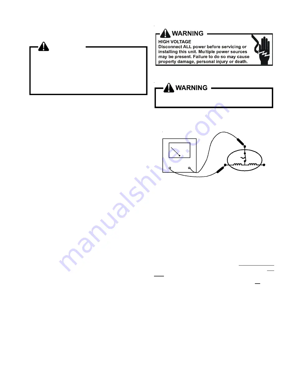
2. Using an ohmmeter, test continuity between terminals S-

R, C-R, and C-S, on single phase units or terminals T2,
T2 and T3, on 3 phase units.

S

R

C

COMP

OHMMETER

TESTING COMPRESSOR WINDINGS

If either winding does not test continuous, replace the
compressor.

NOTE: 

 If an open compressor is indicated, allow ample time

for the internal overload to reset before replacing compressor.

S-17B GROUND TEST

If fuse, circuit breaker, ground fault protective device, etc., has
tripped, this is a strong indication that an electrical problem
exists and must be found and corrected. The circuit protective
device rating must be checked, and its maximum rating
should coincide with that marked on the equipment name-
plate.

With the terminal protective cover in place, it is acceptable to
replace the fuse or reset the circuit breaker ONE TIME ONLY
to see if it was just a nuisance opening.  If it opens again, DO
NOT continue to reset.

Disconnect all power to unit

, making sure that 

all

 power

legs are open.

1. DO NOT remove protective  terminal cover. Disconnect

the three leads going to the compressor terminals at the
nearest point to the compressor.

2. Identify the leads and using a Megger, Hi-Potential Ground

Tester, or other suitable instrument which puts out a
voltage between 300 and 1500 volts, check for a ground
separately between each of the three leads and ground
(such as an unpainted tube on the compressor).  Do not
use a low voltage output instrument such as a volt-
ohmmeter.

Summary of Contents for ASC13018

Page 1: ...ps with R 22 Refrigerant Blowers Coils Accessories This manual is to be used by qualified professionally trained HVAC technicians only Goodman does not assume any responsibility for property damage or...

Page 2: ...you assume responsibility for any personal injury or property damage which may result WARNING This unit should not be connected to or used in conjunction with any devices that are not design certifie...

Page 3: ...s Ensure the pressure rating meets or exceeds 400 lbs When in doubt do not use cylinder WARNING In either of these instances an electrical short between the terminal and the compressor housing may res...

Page 4: ...ons G S C 13 036 1 A A Brand Name G Goodman Brand Amana Brand Distinctions S Goodman Brand High Feature Set Models A Amana Brand Product Category S Split System Unit Type C Condenser R 22 H Heat Pump...

Page 5: ...5 tons 024 2 tons 030 2 5 tons 036 3 tons 042 3 5 tons 048 4 tons 060 5 tons 070 5 tons 090 7 5 tons 120 10 tons C KL 036 2 A Electrical Supply Unit Type E CommercialAirConditioner K AirConditioner P...

Page 6: ...ner K AirConditioner P Heat Pump Product Category C Split System 1 208 230V 60Hz 1ph 2 220 240V 50Hz 1ph 3 208 230V 60Hz 3ph 4 308 415V 50Hz 3ph Revision NominalCapacity 018 1 5 tons 024 2 tons 030 2...

Page 7: ...n A Initial Release THIS NOMENCLATURE IS TO BE USED AFTER JULY 2006 THIS NOMENCLATURE IS TO BE USED TRHOUGH JULY 2006 A W U F 3642 1 6 A A Electrical Supply Expansion Device Application C Ceiling Moun...

Page 8: ...21 Furnace Cabinet D Fits 24 1 2 Furnace Cabinet N Does Not Apply Horizontal Slab Coils Expansion Device F Flowrator Revision A Initial Release Nominal Capacity Range 13 SEER 1824 1 1 2 2 tons 3030 2...

Page 9: ...X X X X X CSR U 1 Hard Start Kit X X X X CSR U 2 Hard Start Kit X X X X CSR U 3 Hard Start Kit X X Model Description ASC13018 ASC13024 ASC13030 ASC13036 ASC13042 ASC13048 ASC13060 OT18 60A Outdoor The...

Page 10: ...Kit x x OT18 60A Outdoor Lockout Stat OT EHR18 60 Emergency Heat relay kit CSR U 1 Hard Start Kit x x CSR U 2 Hard Start Kit x x x CSR U 3 Hard Start Kit x x Model Description CKL18 CKL24 CKL30 CKL36...

Page 11: ...ORATOR COIL 1 4 FLARE CONNECTION BULB SUCTION LINE EXPANSION VALVE REMOVE BEFORE INSTALLING EXPANSION VALVE SEAL SUPPLIED W KIT SEAL SUPPLIED W KIT BULB TO BE LOCATED AT 10 OR 2 O CLOCK TAILPIECE 3 8...

Page 12: ...HERMOSTAT WIRE SHORT CYCLE PROTECTOR YELLOW 1 BLACK 1 Y1 Y2 R1 R2 Y C UNIT TERMINAL BOARD CONTACTOR ASC01A ANTI SHORT CYCLECONTROLKIT Install Line Thermostat Here Install Line Thermostat Here Wire Nut...

Page 13: ...X X CHPF30306 X X CHPF36426 X X CSCF1824N6 X X CSCF303N6 X X CSCF3642N6 X X X NO HEAT KIT HKR 03 HKR05 C HKR 06 HKR 08 C HKR 10 C HKR 15C HKR 20C HKR 21C HKR3 15 HKR3 20 MBR0800AA 1AA X X X X X MBR12...

Page 14: ...t the compressorcenter COILS AND BLOWER COILS MBR MBEblowercabinetsaredesignedtobeusedasatwo piece blower and coil combination MBR MBE blower sec tions can be attached to cased evaporator coil This tw...

Page 15: ...d itcontinuestogiveup heat which subcools the liquid and it is ready to repeat the cycle HEATING The heating portion of the refrigeration cycle is similar to the coolingcycle Byenergizingthereversingv...

Page 16: ...door Coil Accumulator Bi Flow Filter Dryer Outdoor Coil Thermostatic Expansion Valve Check Valve Reversing Valve De Energized Indoor Coil Accumulator Bi Flow Filter Dryer Outdoor Coil Thermostatic Exp...

Page 17: ...ng mode the orifice moves back off its seat allowingrefrigeranttoflowunmeteredaround the outside of the orifice EXPANSIONVALVE CHECKVALVEASSEMBLY INCOOLINGOPERATION EXPANSIONVALVE CHECKVALVEASSEMBLY I...

Page 18: ...ndoor Coil Outdoor Coil Thermostatic Expansion Valve COOLING CYCLE CONDENSING UNIT In the cooling mode the orifice is pushed into its seat forcing refrigerant to flow through the metered hole in the c...

Page 19: ...elow a specific ambient temperature setting i e break even temperature during heating When used in this manner the Y heat demand is switched to the W1 input to the furnace by the outdoor thermostat an...

Page 20: ...est Motor Windings S 16 Improper Cooling Anticipator Check Resistance of Anticipator S 3B Shortage of Refrigerant Test For Leaks Add Refrigerant S 101 103 Restricted Liquid Line Remove Restriction Rep...

Page 21: ...CM Motor Windings 33 S 16D ECM CFM Adjustments 33 S 16E Checking GE X13 Motors 34 S 17 CheckingCompressorWindings 35 S 17A Resistance Test 35 S 17B GroundTest 35 S 17D OperationTest 36 S 18 Testing Cr...

Page 22: ...nsofundersized wirecancauselowvoltage Ifwiresizeisadequate notify the local power company in regard to either low or high voltage REMOTE CONDENSING UNITS BLOWER COILS VOLTAGE MIN MAX 208 230 198 253 1...

Page 23: ...TS OPTIONS Troubleshooting Encoded Two Stage Cooling Thermostats Options TEST FUNCTION SIGNAL OUT SIGNAL FAN S T E T S1 S1 S1 S2 S2 S2 S3 S3 S3 R COM LOW SPEED COOL LO SPEED COOL HI SPEED COOL LO SPEE...

Page 24: ...pproximatelythree minutes before resetting 1 Remove wire from Y1 terminal 2 Wait for approximately four 4 minutes if machine was running With power ON WARNING Line Voltage nowpresent 1 Apply 24 VAC to...

Page 25: ...relay or contactor S 8 CHECKING CONTACTOR CONTACTS DISCONNECTELECTRICALPOWERSUPPLY WARNING Disconnect Electrical Power Supply 1 Disconnectthewireleadsfromtheterminal T sideofthe contactor 2 With powe...

Page 26: ...electrical box of any residential condensing unit that has a Copeland Scroll compressor inside Once attached Comfort Alert provides around the clock monitoring for common electrical problems compress...

Page 27: ...formation Yellow ALERT Locked Rotor 1 Run capacitor has failed Flash Code 4 2 Low line voltage contact utility if voltage at disconnect is low 3 Excessive liquid refrigerant in compressor 4 Compressor...

Page 28: ...ight dimming within the home Only hard start kits approved by Amana brand or Copeland should be used Kick Start and or Super Boost kits are not approved start assist devices Thedischargecheckvalveclos...

Page 29: ...o and slowly returnstoinfinity Startcapacitorwithbleedresistorwill not return to infinity It will still read the resistance of the resistor B Shorted indicator swings to zero and stops there replace C...

Page 30: ...5 at the power connector If no voltage is present 3 Check the unit for incoming power See section S 1 4 Check the control board See section S 40 5 Iflinevoltageispresent reinsertthe5 pinconnectorand...

Page 31: ...R G Turn power OFF prior to repair Wait 5 minutes after disconnecting power before opening motor Handle electronic motor control with care Motor rocks but won t start Loose motor mount Blower wheel n...

Page 32: ...wer OFF prior to repair Wait 5 minutes after disconnecting power before opening motor Handle electronic motor control with care Blower won t shut off Current leakage from controls into G Y or W Check...

Page 33: ...E product uses a General Electric ECMTM motor This motor provides many features not available on the traditional PSC motor These features include ImprovedEfficiency Constant CFM Soft Start and Stop Im...

Page 34: ...ged electric heat cut jumper PJ4 on the control board S 16E CHECKING GE X13TM MOTORS The GE X13TM Motor is a one piece fully encapsulated 3 phasebrushlessDC singlephaseACinput motorwithball bearing co...

Page 35: ...otoramperage andwindingtemperature Highmotortemperatureoramper age heats the disc causing it to open breaking the common circuit within the compressor on single phase units Heat generated within the c...

Page 36: ...thecause for failure is somewhere else in the system B If the compressor fails to start replace COPELAND COMPRESSOR 03 A 12345 L YEAR MONTH SERIAL NUMBER PLANT S 18 TESTING CRANKCASE HEATER OPTIONAL I...

Page 37: ...he EBTDR board These terminals are used to connect the unused leadsfromtheblowermotorandhavenoaffectontheboard s operation SEQUENCE OF OPERATION This document covers the basic sequence of operation fo...

Page 38: ...r the first stage heat demand Note If more than two heater elements are on the heater assembly it will contain a second heat sequencer HR2 which will control the 3rd and 4th heater elements if availab...

Page 39: ...tion 2 1 On a demand for heat the room thermostat energizes W1 and 24Vac is supplied to terminal E W1 of the VSTBinsidetheMBEandAEP units TheVSTBwillturn on the blower motor and the motor will ramp up...

Page 40: ...contains a second heater element HR1 will contain a second set of contacts M3 and M4 which will close to turn on heater element 2 Note If more than two heater elements are on the heater assembly it w...

Page 41: ...ion manual suppliedwiththeblowercoil ortheblowerperformancetable in the service manual shows the CFM for the static mea sured Alternately the system CFM can be determined by operat ingtheelectricheate...

Page 42: ...er test the element for continuity no reading indicates the element is open Replace as necessary S 100 REFRIGERATION REPAIR PRACTICE DANGER Always remove the refrigerant charge in a proper manner befo...

Page 43: ...e s with the compressor open with the suction line of the comprssor closed or severely restricted WARNING 1 Connect the vacuum pump vacuum tight manifold set with high vacuum hoses thermocouple vacuum...

Page 44: ...suction valve core remove hose and reinstall both valve core caps 6 Check system for leaks NOTE Thischargingprocedurecanonlybedoneinthe cooling mode of operation Early production a mod els only All mo...

Page 45: ...needforanexternalcheckvalveandbypassloop Thethreeforceswhichgoverntheoperationofthevalveare 1 the pressure created in the power assembly by the feeler bulb 2 evaporatorpressure and 3 theequivalentpres...

Page 46: ...le superheat SUPERHEAT ADJUSTMENT The expansion valves used on Amana brand coils are factory set and are not field adjustable If the superheat setting becomes disturbed replace the valve On systems us...

Page 47: ...flow into an evaporator coil The amount of refrigerant that flows through the capillary tube restrictororificeisregulatedbythepressuredifference between the high and low sides of the system In the coo...

Page 48: ...OTICE Violation of EPA regulations may result in fines or other penalties Now determine if a burn out has actually occurred Confirm byanalyzinganoilsampleusingaSporlanAcidTestKit AK 3 or its equivalen...

Page 49: ...line size to 3 8 is critical since an increased refrigerant charge level from having a larger liquidlinecouldpossiblyshortenacompressor slifespan 3 Single Stage Condensing Unit The maximum length of...

Page 50: ...le 9 Installation Requirements 1 In a completely horizontal installation with a long line set wheretheevaporatorisatthesamealtitudeas orslightly below the condenser the line set should be sloped towar...

Page 51: ...0 F at any time Wrap the reversing valve with a large rag saturated with water Re wet the rag and thoroughly cool the valve after eachbrazingoperationofthefourjointsinvolved Thewetrag around the rever...

Page 52: ...oilandthenegativeprobe above the coil 2 A direct reading can be taken of the static pressure drop across the coil 3 Consult proper table for quantity of air STATIC PRESSURE DROP Ifthetotalexternalstat...

Page 53: ...P2 4 K1 OT NO Y P2 9 CALL FOR 2ND STAGE COMPRESSOR Y2 1 0K G FURN P2 1 C OT C C SECOND STAGE COMPRESSOR OUTPUT G CALL FOR EMERGENCY HEAT W1 FURN W2 HP F1 3A OT NC 24VAC 2ND STAGE COMPRESSOR DEMAND OUT...

Page 54: ...age Electric Heat RED EMERGENCY HEAT RELAY 1 4 2 BLUE WHITE BLACK BROWN THERMOSTAT OT EHR18 60 2 1 From Air Handler C G W2 R C R W2 O Y From Outdoor Unit C G W2 E R O Y Indoor Thermostat W3 B L U E G...

Page 55: ...or Unit C G W2 E R O Y Indoor Thermostat W3 W3 B L U E G R E E N W H I T E R E D B R O W N B L U E R E D W H I T E O R A N G E Y E L L O W 15kw and Above with Two OT EHR18 60 s Two Stage Electric Heat...

Page 56: ...ATOR MOTOR ELECTRONIC BLOWER TIME RUN CAPACITOR SR EM EBTDR RC BK RD BL YL BLUE BLACK RED YELLOW COMPONENT CODE BROWN PURPLE GREEN PU BR GR FEMALE PLUG CONNECTOR MALE PLUG CONNECTOR NOTE 2 TRANSFORMER...

Page 57: ...G NO K1 USE COPPER OR ALUMINUM WIRE EQUIPMENT GROUND 3 5 2 1 4 TR PC PU L1 L2 BL W BR SR PK G W BR BL PU R BK R R R BK BL BL R 208 240 24V BL R M6 M5 RS2 W BR BL BL L1 L2 BK BK R R Y Y Y M8 M7 BL BL B...

Page 58: ...ATIONS CONNECT THERMOSTAT TO Y Y2 ONLY TAPE OR REMOVE Y1 CONNECTION CONNECT CONDENSING UNIT TO YCON C 6 RED WIRES TO BE ON TRANSFORMER TERMINAL 3 FOR 240 VOLTS AND ON TERMINAL 2 FOR 208 VOLTS 1 FOR HE...

Page 59: ...DENSER COM W2 O ED W1 OUTDOOR HEATPUMP W W2 R W BL OTC OT1 C OT2 O E W1 BR BL Y BL Y YCON TO CONDENSER C PL2 3 1 2 BR Y W BL BR R PK G Y1 C W2 R TO Y Y2 G EM BK R G BL 4 5 6 7 8 9 W R R BL COM BL 5 TR...

Page 60: ...r 240 volts and on terminal 2 for 208 volts 2 See composite wiring diagrams in installationinstructions for proper low voltage wiring connections Notes DELAY RELAY RELAY EVAPORATOR MOTOR ELECTRONIC BL...

Reviews: