


Always
O
n UPS Systems
M0703_NX_Series_Operators_Manual
V1.25
2012-06-12 50
•
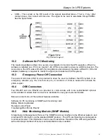
COM – This contact is the OR result of the signals described above. That is, if any other
contact closes, this contact will close too. The signal to be read is selectable through SWR2.
See the figure below.
10.2
Software for PC Monitoring
The monitoring software allows for a server or workstation to monitor the UPS operation. When the
software is installed on a PC it can monitor 1-99 UPS’s connected in series via a DB9 connection. The
connector on the UPS side is RS-485 (for long distance transmission) therefore a RS-485
Ù
RS-232
adapter (hardware) is required to modify the signal (not included with UPS system).
10.3
Emergency Power Off Connection
Two pairs of terminals (CNR 3) are provided to allow the user to shutdown the UPS system in an
emergency situation (e.g. fire, short circuit, etc.). A minimum of 10mA is needed for activate the
photo-coupler.
10.4 DB9
Connectors
Four RS-485 and one RS-232 are provided to communicate with more sophisticated optional
communication modules. Each connector is dedicated to one type of external module.
Below is a list of some of the optional features available:
Software for PC monitoring or SNMP (web monitoring) card
Battery Monitoring Module
Remote Control Panel
Transferring RS-485 into RS-232
10.5
Web Monitoring Module (SNMP Module)
Simple Network Management Protocol. The SNMP Card is an Interface to the Ethernet network, and
provides UPS information via the standard SNMP protocol. The UPS can therefore be managed via
an internet browser. This information can be used to determine the state of the UPS and guarantee
safe and orderly shutdown of servers and workstations when needed.
Figure 10.1.2
Dry Contact Layout