


Chapter 1 - Product Description
Specifications
BreezeMAX PRO 5000 CPE
6
Product Manual
1.2.2
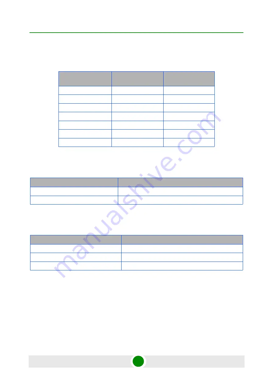
Sensitivity
1.2.3
IDU/ODU Communication
1.2.4
Data Communication (Ethernet Port)
Table 1-2: Sensitivity
Modulation & Coding
Sensitivity (dBm)
@ 5 MHz BW
Sensitivity (dBm)
@ 10 MHz BW
QPSK 1/2
-96
-93
QPSK 3/4
-93
-90
16QAM 1/2
-89
-86
16QAM 3/4
-86
-83
64QAM 2/3
-81
-78
64QAM 3/4
-80
-77
64QAM 5/6
-79
-76
Table 1-3: ODU/ODU Communication
Item
Details
Cable Type
Category 5E, Outdoor Data Cable, Double Jacket, 4x2x24# FTP
Maximum Length
90 meter
Table 1-4: Data Communication (Ethernet Port)
Item
Details
Standard Compliance
IEEE 802.3 CSMA/CD
Maximum Frame Size (including 4 CRC bytes)
1522 Bytes
Speed
10/100 Mbps, Half/Full Duplex with Auto Negotiation
Summary of Contents for BreezeMAX PRO 5000 CPE
Page 1: ...BreezeMAX PRO 5000 CPE Product Manual Software Version 1 5 April 2010 P N 215643...
Page 17: ...Tables BreezeMAX PRO 5000 CPE xvii Product Manual Table 4 3 CPE Parameters Summary 85...
Page 18: ...1 Chapter Product Description...
Page 27: ...2 Chapter Installation...
Page 46: ...3 Chapter Commissioning...
Page 58: ...4 Chapter Operation...
Page 105: ...A Appendix Troubleshooting...
Page 109: ...Glossary...


