Supervisor 3500 Installation Instructions
PUD3673R1-1
For assistance: [email protected] +1 (909) 591-8431
Page 15
Baseplate Assembly (Optional)
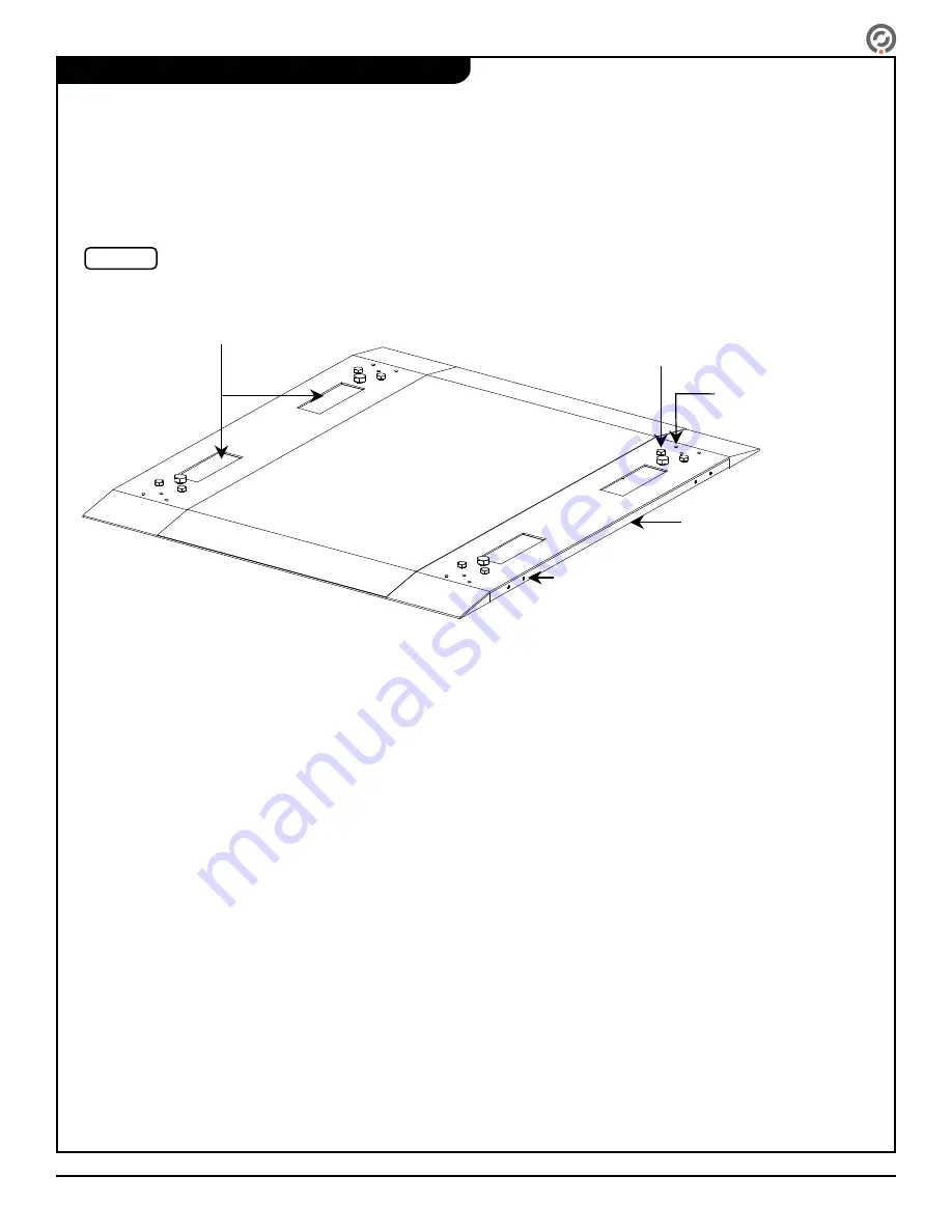
An optional SU3500 baseplate may be purchased with the SU3500 turnstile. A baseplate enables installation of the SU3500
turnstile on a solid foundation without the need to drill holes in the ground. The baseplate also provides concealed conduit channels
for wiring all power and communication cables. Baseplates come in different sizes and may be bridged together with other
baseplates for multiple turnstile lanes. The following information will guide the installer in assembling the baseplate:
Examine the area with a measuring tape and carefully mark the location where the baseplate(s) will be placed. An external power
source and external data cables (required for GateKeeper and external controls), must be accessible and provided to the turnstile.
The side plate on the baseplate must be removed in order to provide external power/data (or the side plate may be drilled with
appropriate holes as needed for concealment). Determine which side plate to remove and remove it by unfastening the (4) screws
as shown in [Figure 12].
Place the baseplate carefully in the marked location. The installation process continues in the following sections. Follow the
instructions there in order to pull the appropriate cables through the conduit openings.
For multiple lanes, baseplates may be attached together. Holes are provided for bridging multiple baseplates together. The side
plate must be removed in order to bridge the baseplates together side by side. Secure the baseplates side by side by fastening
the (6) screws provided to the link from the other baseplate (a link is provided for multiple lane baseplates).
Anchor Location.
Holes for Bridging
Multiple
Baseplates.
Conduit Holes for Power and Communication Cables
(Use Separate Conduits for Power and Communication Cables).
Unfasten Screws on Side Plate for
External Power/Data Source.
FIGURE 3.2.2 – SU3000 Portable
Baseplate
Side Plate.
Conduit holes for power and communication cables.
(Use separate conduits for power and communication
cables)
Anchor Locations
Holes for bridging multiple
baseplates
Side Plate
Side Plate
Screws
Fig. 12
Baseplate


