INSTALLATION AND OPERATION MANUAL | CUL11 CONTROL UNIT
4
4
PRODUCT DESCRIPTION
The section of electric mains to which the product is connected should be equipped with a pro-
tection device (three-pole circuit-breaker). The distance between terminals in the protective
cutout device should be at least 3 mm.
Parameters of electric cables used (section, number of wires, length and other) should comply
with the connection diagram, device power, laying distance, laying method, ambient conditions.
Use a multicore cable with double insulation.
Electric cables should be protected against contact with any rough and sharp surfaces, use
corrugated tubes and cable glands for laying cables.
The company reserves the right to change this manual and product construction without prior
notice, however maintaining the same functionality and purpose.
Instruments and materials used should be complete, in good condition and comply with the
current safety regulations, standards and instructions.
The company does not directly control the installation of the product and automation devices,
its maintenance and operation, and cannot be responsible for the safety of product installation,
operation and technical maintenance.
Recommendations described in this manual should be considered as an example, as the place
of installation can differ. The task of the installer is to make the most appropriate decision.
The installer is responsible for work on the entire system. In his work, he should observe the cur-
rent regulations and standards (e.g., DIN 1986, EN 12050, EN 1398). He is also responsible for main-
tenance of technical documentation of the entire system that is supplied with the equipment.
The content of this manual cannot be used as grounds for legal challenges.
2.
PRODUCT DESCRIPTION
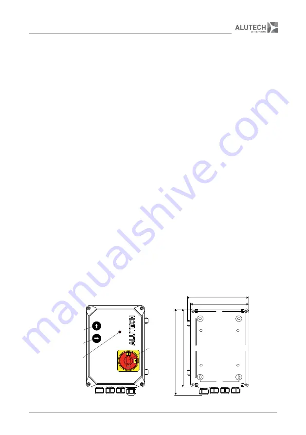
The unit is designed to control components of the transfer equipment. Directly for the transfer
platform with telescopic (extensible) ramp equipped with 2-valve hydraulic unit. On-off switch
1
(
fig.
1), control buttons
2
and
3
, indication
LED 4
are located on the cover of control unit housing.
The control unit is supplied with a cable 5G 1.5 sq. mm for power connection (1 m long / without
plug). When being manufactured, the dock levellers are fitted with 4G 1 sq. mm cable for con-
nection of the electric motor for the hydraulic unit and two 2 × 1 sq. mm cables with connectors
for connection of hydraulic unit valves. The Manufacturer chooses the necessary length of the
cables depending on the size of a dock leveller. The set of cables СTL07-2 consists of 7 m long
cables. The set of cables СTL10-2 consists of 10 m long cables.
190
28
0
25
4
190
239
180
165
120
1
4
2
3
Figure 1
. Control unit (dimensions are given in millimeters)
Summary of Contents for CUL11
Page 1: ...CONNECTION AND OPERATIONAL MANUAL Control unit CUL11 English 2020 www alutech group com ...
Page 2: ......
Page 4: ......
Page 17: ...INSTALLATION AND OPERATION MANUAL CUL11 CONTROL UNIT 15 15 SPECIAL NOTES ...
Page 18: ......
Page 19: ......


