T1KE34/38 / T2KE3316 Installation Guide
- 3 -
T1KE34: Configuration of Kisi Pro Controllers:
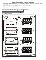
1. Fasten mounting magnets (provided) to Kisi Pro Controllers with screws and spacers (provided) using the controllers’ mounting holes
(Fig. 2, pg. 3)
.
2. Attach mounting magnets to TLU1 in the approximate position as shown below
(Fig. 2, pg. 3)
.
Note:
Kisi Pro Controllers should be properly oriented.
Please make sure that they are mounted correctly, as shown in
Fig. 2
below.
3. Fasten TLU1 backplane to Trove1 enclosure utilizing hardware (provided).
Access Controller Position Chart for the Following Models:
Kisi
Pem Mounting
Pro Controller
A
Fig. 2 -
T1KE34 Configuration
ACM4(CB)
TRG
TRIGGER
INPUT
ACM4
ACCESS POWER
CONTROLLER
LED1
LED2
LED3
LED4
MAIN
OUTPUT 1
NC C NO COM NC C NO COM
NC C NO COM NC C NO COM
OUTPUT 2
OUTPUT 3
IN GND
1
IN GND
2
IN GND
3
IN GND
4
OUTPUT 4
--
+
CONTROL
--
+
POWER
+INP-
T +RET
-
INTERF
ACE
NO C NC
FA
CP
A
L
G
N
AC
DC
BA
T
+ BAT -
+ DC -
NC
C
NO
NC
C
NO
BA
T F
AIL
AC F
AIL
Power Supply


