background image

- 6 - 

eBridge4SK

network administrator and repeat the email setup sets. 
After all fields have been programed click the button labeled 

Reboot Server. A dialog box will display “Please allow up to 30 sec. for server to reboot”. Click OK.

All programmed information will be saved after the server has rebooted.

Setup:

Click on the tab labeled 

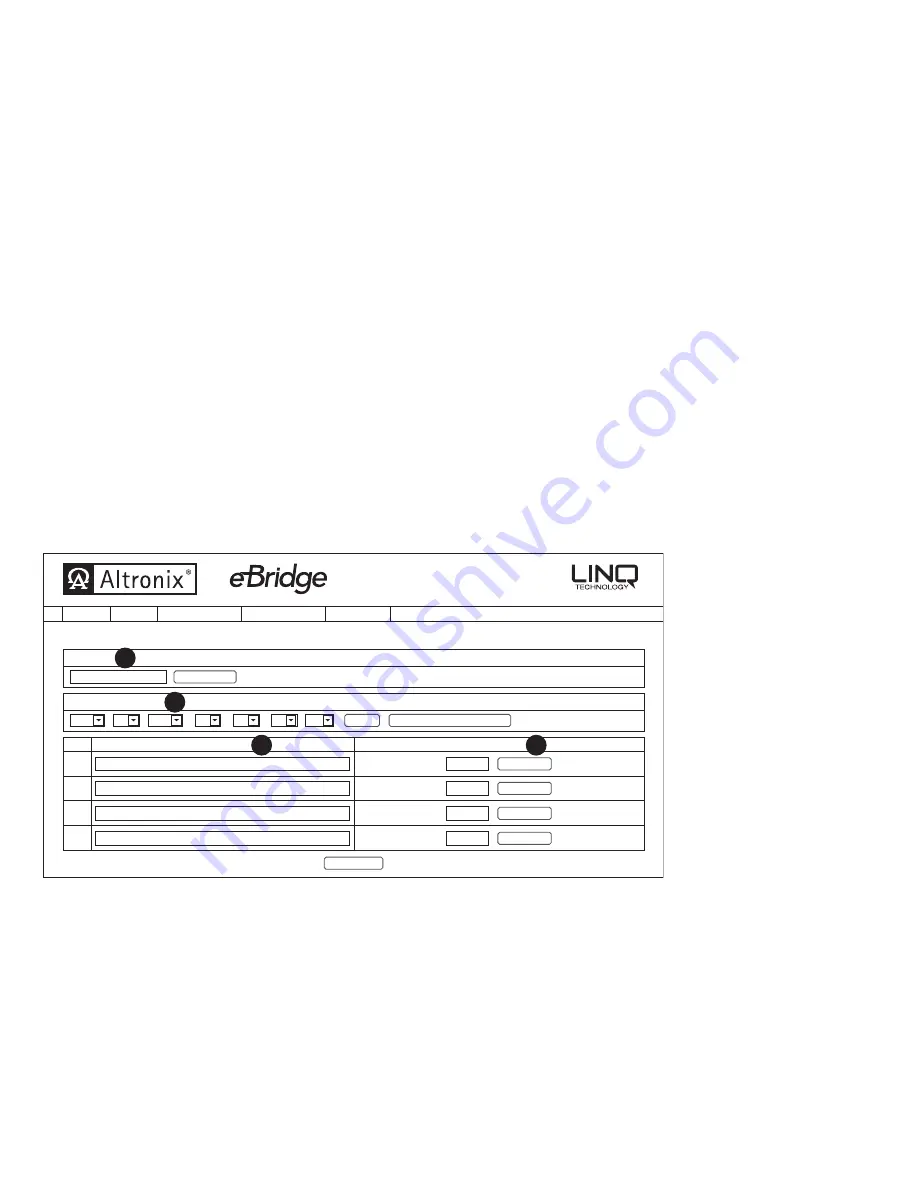
Setup. The eBridge4SPT setup page will open. In this screen the Site ID, Date/Time and Port identification are setup, along with the

ability to enable and disable individual ports.
Site ID (Fig. 3a, pg. 6): Enter a descriptive name that will identify the location of the eBridge4SPT. The Site ID will appear in both the trap message and email 
notifications. 
Date/Time (Fig. 3b, pg. 6): Time and Date can be entered two different ways manually or by syncing the date and time with the host computer.
Manual setup (Fig. 3b, pg. 6)Individually select the appropriate information for each of the required field then click Update. This will update time of the 
eBridge4SPT to the programmed information. The manual setup can be used when programming devices installed in one time zone and monitored in another. 
Sync Setup (Fig. 3b, pg. 6): Clicking the button labeled Sync Date/Time with computer will set the eBridge4SPT to the time of the host computer. 
Port ID (Fig. 3c, pg. 6): Enter a descriptive name and/or location of the device connected to the port.
Port Status (Fig. 3d, pg. 6): Individual ports can be enabled or disabled by clicking the button labeled Enable Port/Disable Port. This feature allows unused 
ports to be disabled and also can be used to reboot a connected device by cycling power OFF and ON.
After all fields have been programmed click on the button labeled 

Save Settings.

Fig. 3

Setup

eBridge4SPT

Jul

Site ID:

Save Settings

Trap Receiver Settings:

Port

1

Port ID

Port Status

Update Site ID

RJ Sports Wear

Update

Disable Port

Sync Date/Time with computer

Enabled

Main Entrance

2015

15

32

53

am

9

[              :              :                            ]

Management Interface

Events Log

v1.99.22

Security Settings

Network Settings

Setup

Status

2

Disable Port

Enabled

Production

3

Disable Port

Enabled

Receiving

4

Disable Port

Enabled

Shipping

b.

a.

c.

d.

Summary of Contents for eBridge100SPR

Page 1: ...quipment UL 60950 1 CE approved Input eBridge100SPR 51 56VDC 60W max power eBridge4SPT powered by eBridge100SPR Power Output eBridge4SPT 4 ports PoE 30W per port Total output power 60W Ethernet Connectivity RJ45 auto crossover Wire type 4 pair Cat 5e or better structured cable Distance up to 100m Speed 10 100BaseT half full duplex auto negotiation Coax Distance up to 300m Connectivity BNC RG 59 U ...

Page 2: ...connector marked Coax located on the back of the unit Fig 1 pg 3 c Connect structured cable from PoE PoE cameras devices to RJ45 jacks marked 1 4 Fig 1 pg 3 Note The eBridge is designed to accommodate Megapixel HD720 HD1080 and VGA SD cameras It is important to note that some high resolution and high frame rate cameras may demand faster headend processing ability such as a PC graphics card to pres...

Page 3: ...ings IP Address 192 168 168 168 User Name admin Password admin 1 Set the static IP address for the laptop to be used for programming to the same network IP address as the eBridge4SPT i e 192 168 168 200 the default address of the eBridge4SPT is 192 168 168 168 2 Connect one end of the network cable to the network jack on the eBridge100SPR and the other to the network connection of the laptop Coax ...

Page 4: ...etwork settings will take effect after the server is rebooted Click OK Next click on the button labeled Reboot Server After rebooting the eBridge4SPT will be set in the DHCP mode The IP address will be assigned by the router when the eBridge4SPT is connected to the network It is recommended to have the assigned IP Address reserved to ensure continued access see the network administrator 2 Subnet M...

Page 5: ...end emails via an in house email server email service provider i e Gmail Yahoo or Altronix default email service In house email server 1 From Enter the email address assigned to the eBridge4SPT module by the system administrator 2 Subject Identify the location of the ebridge4SPT i e the Site ID 3 Username Enter the username associated with the eBridge4SPT module email address 4 Password Enter the ...

Page 6: ...ate time of the eBridge4SPT to the programmed information The manual setup can be used when programming devices installed in one time zone and monitored in another Sync Setup Fig 3b pg 6 Clicking the button labeled Sync Date Time with computer will set the eBridge4SPT to the time of the host computer Port ID Fig 3c pg 6 Enter a descriptive name and or location of the device connected to the port P...

Page 7: ...dule The date and time must be synced with the host computer before generating an SSL certificate Using a private SSL certificate and Key Fig 4b pg 7 Private SSL Certificates and Keys must be uploaded using the Altronix Dashboard For additional information refer to the Altronix Dashboard setup user manual section Updating firmware SSL certificate and Key SSL Status Certificate Status Certificate O...

Page 8: ...mit SSL Settings SSL Status Change Username and Password Save Username and Password SSL State Off Turn SSL On Certificate Status Certificate Ok Key Status Key Ok Management Interface Events Log v1 99 22 Security Settings Network Settings Setup Status Fig 4c Events Log Site ID RJ Sports Wear Friday Jul 31 2015 9 01 am Display Refresh Log Fri Jul 31 2015 08 05 03 GMT 0400 Eastern Daylight Time eBrid...

Page 9: ... Submit to save settings Fig 6 Updating Firmware Firmware updates must be done using the Altronix Dashboard For additional information refer to the Altronix Dashboard setup user manual s section Updating firmware SSL certificate and Key Events Log 1 Site ID RJ Sports Wear Friday Jul 31 2015 9 01 am Display Refresh Log Heartbeat Timer Settings Heartbeat Timer Settings Last update Fri Jul 31 2015 09...

Page 10: ...Device Status Active Port Status Enabled Port 1 Main Entrance Site ID RJ Sports Wear Wednesday Jul 15 2015 9 35 am Connection Status OK Management Interface Events Log v1 99 22 Security Settings Network Settings Setup Status d d d rt 162 Site ID WEBVIEW INTERFACE Class Power Watts 6 49 Actual Power Draw Watts 3 90 Device Status Active Port Status Enabled Port 2 Production Class Power Watts 6 49 Ac...

Page 11: ...eBridge4SK 11 Notes ...

Page 12: ... MEMBER Mounting Hardware Included Four 4 rubber pads 8 42 213 87mm 5 23 132 84mm 1 7 43 18mm 8 93 226 82mm Coax SLOC link LED PoE Output 10 100 Base T Fig 9 Rubber Feet Left side B A C eBridge4SPT Chassis Mechanical Drawing Dimensions H x W x D approx 1 7 x 5 23 x 8 93 43 18mm x 132 84mm x 226 82mm Fig 8 Shelf Installation 1 Position and affix rubber pads C included at each corner on the bottom o...

Reviews: