1-28
American-Lincoln Technology
ATS 46/53 Troubleshooting Guide
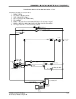
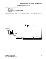
SHAKER MOTOR CIRCUIT (GAS & DIESEL)
SHAKER MOTOR CIRCUIT
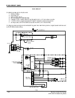
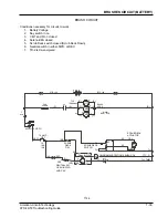
Conditions necessary for circuit to work
1.
Battery Voltage
2.
Key switch on
4.
M2 energized
5.
Hopper switch closed (Hopper Down)
6.
Shaker sw. momentarily closed
7.
TD-1 closed between pins #1 & #6 (For 20 seconds)
8.
Hopper door switch is closed
Start at the shaker motor (Wires #11 & 7c), place (+) meter lead on (Wire #11) & (-) meter lead on (Wire # 7c),
depress the shaker motor switch. If no voltage is present and the gnd. is good then check M2 (Wire #11) if no
voltage on #87 of M2 but there is on #30 of M2 then check #86 on M2. M2 #86 only gets voltage through TD-
1, this 20 sec. timer gets voltage from pin #1 to pin #6 when pin #3 is pulsed by the shaker motor switch. If no
voltage on pin #1,check CB-5 back through the key switch. If no voltage on pin #3 with shaker switch de-
pressed then check the shaker switch, hopper switch, hopper door switch, CB-6 back to the key switch.
12V BATTERY
11
7CC
13
13,13A
13A,13B
7C,7D
7,7A
7,7A
12A,12B
36
36
4
4A,4B
12,12A
19
24A
24,24A
23
23
37
10
10
1E
1,1A,1D,9
M2
SHAKER
MTR. SW.
HOPPER DOOR SW.
(HELD OPEN WHEN
DOOR IS OPEN)
HOPPER SW.
(HELD CLOSED WHEN
HOPPER IS DOWN)
M2
TD-1
CB -1
KEY SWITCH
CB -5
CB -6
15 AMP.
15 AMP.
15 AMP.
BAT.
30
(C)
(C)
(NC)
(NO)
1
6
7
2
3
87
86
85
SHAKER
SHAKER MTR. RELAY
TIMED
SHAKER
MTR.(20 SEC.)
8-10 AMPS.
MTR.
T106


