The appliance must be installed by a qualified service
technician. The oven must be properly grounded in
accordance with the National Electrical Code and
applicable local codes.
Plug the unit into a properly grounded receptacle
ONLY, positioning the unit so that the plug is easily
accessible in case of an emergency. Arcing will occur
when connecting or disconnecting the unit unless all
controls are in the “
OFF
” position.
Proper receptacle or outlet configuration or
permanent wiring for this unit must be installed by a
licensed electrician in accordance with applicable
local electrical codes.
750- and 1000-TH-II models at 208-240V are dual
rated units with a conversion switch mounted under
an access cover on the rear of the oven, near the
power cord.
With the voltage conversion switch in the 200-208V
(UPPER) position, the oven will function properly
with a source voltage of between 200 and 208.
With the voltage conversion switch in the 220-240V
(LOWER) position, the unit will function properly
with a source voltage of between 220 and 240.
NOTE:
ALL 208-240V units are shipped from the
factory with the voltage conversion switch in
the 220-240 position.
All 125V rated units will function properly with a
source voltage of between 100 and 125, 60 Hz.
The 125V rated units are provided with a cord and
plug [NEMA #5-20P]. Have a licensed electrician
install the proper outlet configuration as required for
the unit in accordance with applicable, local electrical
codes. This will assure a safe and trouble-free
installation.
230V:
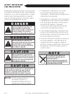
To prevent an electrical shock hazard
between the appliance and other appliances or
metal parts in close vicinity, an equalization-
bonding stud is provided. An equalization
bonding lead must be connected to this stud
and the other appliances / metal parts to
provide sufficient protection against potential
difference. The terminal is marked with the
following symbol.
NOTE:
230V appliances must be connected to
an electrical circuit that is protected by
an external GFCI outlet.
E L E C T R I C A L C O N N E C T I O N
I N S T A L L A T I O N
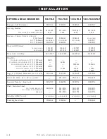
E L E C T R I C A L - 1 0 0 0 - T H - I I
VOLTAGE
PHASE
CYCLE
/
HZ
AMPS
kW
CORD
&
PLUG
120
1
60
16.0
1.9
NEMA
5-20
P
20A - 125V
PLUG
208-240
(
AGCY
)
1
60
14.4
3.0
NO CORD
at 208
1
60
14.4
3.0
OR PLUG
at 240
1
60
11.1
2.7
230
1
50
10.4
2.4
CEE
7/7
220-230V
PLUG
D A N G E R
To avoid electrical shock, this
appliance MUST be adequately
grounded in accordance with local
electrical codes or, in the absence of
local codes, with the current edition
of the National Electrical Code
ANSI/NFPA No. 70. In Canada, all
electrical connections are to be
made in accordance with CSA C22.1,
Canadian Electrical Code Part 1 or
local codes.
Ensure that the voltage conversion switch position
and the available power source match.
PG
. 12
TH-II
INSTALLATION
/
OPERATION
/
SERVICE MANUAL
E L E C T R I C A L - 5 0 0 - T H - I I
VOLTAGE
PHASE
CYCLE
/
HZ AMPS
kW
CORD
&
PLUG
120
1
60
16
1.9
NEMA
5-20
P
20A - 125V
PLUG
208-240
(
AGCY
)
1
60
12.5
3.0
NO CORD
at 208
1
60
10.6
2.2
OR PLUG
at 240
1
60
12.2
2.9
230
1
50
12
2.8
CEE
7/7
220-230V
PLUG
E L E C T R I C A L - 7 5 0 - T H - I I
VOLTAGE
PHASE
CYCLE
/
HZ
AMPS
kW
CORD
&
PLUG
120
1
60
14.2
1.7
NEMA
5-20
P
20A - 125V
PLUG
208-240
(
AGCY
)
1
60
14.4
3.0
NO CORD
at 208
1
60
14.6
3.0
OR PLUG
at 240
1
60
11.2
2.7
230
1
50
10.4
2.4
CEE
7/7
220-230V
PLUG
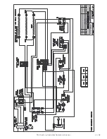
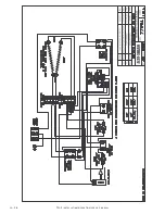
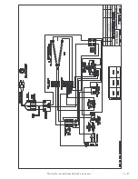
Wire diagrams are located inside the bonnet of the unit.
Summary of Contents for 1000-TH-II Split SERIES
Page 27: ...TH II INSTALLATION OPERATION SERVICE MANUAL PG 25 ...
Page 28: ...PG 26 TH II INSTALLATION OPERATION SERVICE MANUAL ...
Page 29: ...TH II INSTALLATION OPERATION SERVICE MANUAL PG 27 ...
Page 30: ...PG 28 TH II INSTALLATION OPERATION SERVICE MANUAL ...
Page 31: ...TH II INSTALLATION OPERATION SERVICE MANUAL PG 29 ...
Page 32: ...PG 30 TH II INSTALLATION OPERATION SERVICE MANUAL ...


