background image

S I T E I N S T A L L A T I O N

I N S T A L L A T I O N

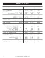
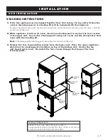
Stacking Configurations

1000-TH-II-Split with 1000-TH-II-Split or 1000-S

750-TH-II with 750-TH-II, 750-TH/III, 750-S, 767-SK or 767-SK/III

500-TH-II with 500-TH-II, 500-TH/III or 500-S

CASTER SET 
SCREW

TOP
MOUNTING
SCREWS

STACKING
POSTS

TOP
MOUNTING
SCREWS

STACKING INSTRUCTIONS

1) If the two appliances were shipped together from the factory, the top unit will have the

casters already removed. A stacking kit will be included with the shipment.

If casters need to be removed: lay the unit on its back, and remove the set screw on each caster. Pull the

casters out of the unit.

2) While appliance is laid on its back, insert one stacking post in each of the four corners

of the upper unit. Secure the stacking posts using one screw and two flat washers that
come with the stacking kit.

Note:

The flange on the stacking posts must face the outside of the unit.

3) Remove the four top mounting screws from the lower unit. Place the upper appliance,

which has the stacking posts installed, on top of the bottom unit. Center the top
unit from front to back. Re-install the four screws through the flange of the four
stacking posts.

TH-II

INSTALLATION

/

OPERATION

/

SERVICE MANUAL

PG

. 9

Summary of Contents for 1000-TH-II Split SERIES

Page 1: ...558 8744 USA CANADA FAX 262 251 7067 800 329 8744 U S A ONLY www alto shaam com MN 29068 02 10 P R I N T E D I N U S A Cooking Holding Oven M a n u a l C o n t ro l Model 500 TH II 750 TH II 1000 TH II 1000 TH II SPLIT INSTALLATION OPERATION MAINTENANCE 1000 TH II Split 1000 TH II 750 TH II 500 TH II ...

Page 2: ... 16 Protecting Stainless Steel Surfaces 16 Cleaning Agents 16 Cleaning Materials 16 Equipment Care 17 Clean Daily 17 Clean the Door Vents 17 Check Overall Condition of Oven 17 Sanitation Sanitation Food Safety 18 Internal Food Product Temperatures 18 Service Thermostat Indicator Light Sequence 19 Thermostat Calibration 19 Trouble Shooting 20 Exterior Service View 21 Exterior Service Parts List 22 ...

Page 3: ... the Alto Shaam service department if you have any questions concerning installation operation or maintenance NOTE All claims for warranty must include the full model number and serial number of the unit U N PA C K I N G 1 Carefully remove the appliance from the carton or crate NOTE Do not discard the carton and other packaging material until you have inspected the unit for hidden damage and teste...

Page 4: ...t can or will cause minor personal injury property damage or a potential unsafe practice if the warning included with this symbol is ignored C A U T I O N Used to indicate the presence of a hazard that can or will cause minor or moderate personal injury or property damage if the warning included with this symbol is ignored D A N G E R Used to indicate the presence of a hazard that WILL cause sever...

Page 5: ...den vapor resulted in a total of 0 55 milligrams per cubic meter with no visible smoke and is considered representative of all oven models in the line Based on these results hood installation and or outside venting should not be a requirement in most areas Verify local codes for locations where more restrictive codes are applicable MINIMUM CLEARANCE REQUIREMENTS COMBUSTIBLE SURFACES NON COMBUSTIBL...

Page 6: ...N 21 532mm with optional bumper 31 13 16 807mm with optional 2 1 2 casters 35 3 16 894mm with optional 5 casters 34 7 16 873mm with optional 6 legs 33 1 2 850mm with 3 1 2 Casters 19 482mm 16 406mm 28 1 4 716mm 18 1 8 460mm 29 7 8 758mm with optional bumper 41 1 2 1054mm 44 1 16 1118mm with optional bumper 58 1 4 1479mm Pass Through Option 28 1 2 724mm 21 15 16 556mm 26 3 4 678mm 12 1 4 310mm 30 7...

Page 7: ...3 1 2 casters 31 13 16 807mm with optional 2 1 2 casters 35 1 4 894mm with optional 5 casters 34 7 16 874mm with optional 6 legs Electrical Connection Shown with optional bumper 34 7 8 886mm 56 15 16 1445mm 79 2006mm Pass Through Design 34 864mm Pass Through 26 15 16 683mm 31 3 4 805mm 14 3 4 373mm 30 7 8 784mm electrical connection 28 5 8 726mm with optinal bumper Electrical Connection 750 TH II ...

Page 8: ... with optional bumper 11 5 16 287mm 34 1 2 876mm with optional bumper 53 5 8 1361mm with optional bumper 51 1 4 1302mm 72 3 4 1847mm Pass Through Design Electrical Connection 75 3 8 1915mm with optional 3 1 2 89mm casters 76 1 16 1932mm approx with optional 6 152mm legs 76 3 4 1949mm with 5 Casters 41 11 16 1059mm with 5 Casters 35 1 16 890mm 32 3 8 822mm Electrical Connection 35 1 16 890mm 74 1 8...

Page 9: ...ional bumper 53 5 8 1361mm with optional bumper 51 1 4 1302mm 72 3 4 1847mm Pass Through Design Electrical Connection 39 3 8 999mm with optional 2 1 2 64mm casters 41 11 16 1059mm with optional 5 127mm casters 41 1 16 1042mm approx with optional 6 152mm legs 35 1 16 890mm 23 1 2 596mm PRODUCT PAN CAPACITY 120 lb 54 kg MAXIMUM VOLUME MAXIMUM 60 QUARTS 76 LITERS 1000 TH II SPLIT WEIGHT NET 225 lb 10...

Page 10: ...Pan STANDARD WITH DRAIN 1 7 16 37mm STANDARD WITH DRAIN 1 11 16 43mm STANDARD WITH DRAIN 1 7 8 48mm WITHOUT DRAIN 1 7 16 37mm WITHOUT DRAIN 1 7 8 48mm EXTRA DEEP 4 102mm 14813 11898 14831 11906 5005616 11906 15929 5005616 11906 15929 Legs 6 152mm Stemmed SET OF FOUR 5011149 5011149 5011149 5011149 Pan Grid Wire 18 X 26 PAN INSERT PN 2115 PN 2115 PN 2115 Security Panel w Key Lock 5006787 5004750 50...

Page 11: ... need to be removed lay the unit on its back and remove the set screw on each caster Pull the casters out of the unit 2 While appliance is laid on its back insert one stacking post in each of the four corners of the upper unit Secure the stacking posts using one screw and two flat washers that come with the stacking kit Note The flange on the stacking posts must face the outside of the unit 3 Remo...

Page 12: ...ved NOTE Failure to properly level this oven can cause improper function and will result in the uneven baking with products consisting of semi liquid batter RESTRAINT REQUIREMENTS MOBILE EQUIPMENT Any appliance that is not furnished with a power supply cord but that includes a set of casters must be installed with a tether Adequate means must be provided to limit the movement of this appliance wit...

Page 13: ...HAZARD THAT CAN CAUSE PERSONAL INJURY Item Description Qty 1 Double Sided Tape 1 2 Drip Tray Holder 1 3 8 32 x 1 4 Phil Screw 3 4 Drip Tray 1 1 Poke holes through double sided tape which is attached to the back of drip tray holder 2 Remove backing on double sided tape 3 Put screws through holes and attach drip tray holder to unit 4 Optional apply a line of food grade silicone caulk along top edge ...

Page 14: ...ck hazard between the appliance and other appliances or metal parts in close vicinity an equalization bonding stud is provided An equalization bonding lead must be connected to this stud and the other appliances metal parts to provide sufficient protection against potential difference The terminal is marked with the following symbol NOTE 230V appliances must be connected to an electrical circuit t...

Page 15: ...on position and set the thermostat to 300 F 149 C 3 Allow the oven to cycle for approximately 2 hours or until no odor is detected PREHEATING Always preheat the oven for a minimum of 20 minutes before cooking product Follow the operating instructions indicated on the next page of this manual D A N G E R ENSURE POWER SOURCE MATCHES VOLTAGE STAMPED ON APPLIANCE NAMEPLATE C A U T I O N METAL PARTS OF...

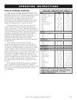
Page 16: ...perational guidelines only For complete instructions see A Guide to Low Temperature Cooking and Holding by HALO HEAT packed with the oven I o O P E R AT I N G I N S T R U C T I O N S COOKING OVEN CHARACTERISTICS The oven is equipped with a special high heat density heating cable Through the Halo Heat concept the heating cable is mounted against the walls of the cooking cavity to provide an evenly ...

Page 17: ...ods however a maximum of 1 to 2 minutes must be the only time period allowed for the initial heat to be released from the product Most Halo Heat Holding Equipment is provided with a thermostat control between 60 and 200 F 16 to 93 C If the unit is equipped with vents close the vents for moist holding and open the vents for crisp holding H O L D I N G T E M P E R A T U R E R A N G E MEAT FAHRENHEIT...

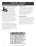
Page 18: ...er rinsing CLEANING AGENTS Use non abrasive cleaning products designed for use on stainless steel surfaces Cleaning agents must be chloride free compounds and must not contain quaternary salts Never use hydrochloric acid muriatic acid on stainless steel surfaces Always use the proper cleaning agent at the manufacturer s recommended strength Contact your local cleaning supplier for product recommen...

Page 19: ... dry Leave doors open until interior is completely dry Replace side racks and shelves 9 Wipe door gaskets and control panel dry with a clean soft cloth 10 Interior can be wiped with a sanitizing solution after cleaning and rinsing This solution must be approved for use on stainless steel food contact surfaces 11 To help maintain the protective film coating on polished stainless steel clean the ext...

Page 20: ...tures of both hot and cold foods is by internal product temperature A quality thermometer is an effective tool for this purpose and should be routinely used on all products that require holding at a specific temperature A comprehensive sanitation program should focus on the training of staff in basic sanitation procedures This includes personal hygiene proper handling of raw foods cooking to a saf...

Page 21: ...g of the bulb results in a change in its volume and alters the accuracy of the thermostat calibration A thermostat should be checked or recalibrated by placing a quality thermal indicator at the center of an empty holding cavity DO NOT CALIBRATE WITH ANY FOOD PRODUCT IN THE CABINET The thermostat should be set and should be allowed to stabilize at that setting for a minimum of one hour Following t...

Page 22: ...hold calibration Oven goes from cooking Hold thermostat Replace hold thermostat temperature to cold Oven will not go into cook cycle Timer or contactor With timer turned ON line when timer and cook thermostat voltage should appear across are ON terminal 2 and 3 of timer If not replace timer If line voltage does appear across terminal 2 and 3 of timer it should also appear across holding coil of co...

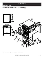
Page 23: ...3 23 9 24 7 31 15 5 6 16 1 27 25 21 12 22 27 26 11 10 2 32 33 A A SECTION A A 3 30 18 14 28 4 17 20 EXTERIOR VIEW 750 TH II SHOWN TH II INSTALLATION OPERATION SERVICE MANUAL PG 21 A Part numbers and drawings are subject to change without notice ...

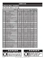
Page 24: ...4 2 16 CASTER 3 1 2 SWIVEL W BRAKE CS 25675 2 CS 25675 2 CASTER 5 SWIVEL W BRAKE CS 24875 2 17 COVER HINGE CV 22171 2 CV 22171 2 CV 22171 2 18 GUARD CAPILLARY GD 2450 1 GD 2450 1 GD 2450 1 19 GASKET BONNET GS 23622 1 GS 23622 1 GS 23622 1 20 GASKET DOOR GS 22950 1 GS 22951 1 GS 22952 1 21 HANDLE OFFSET MAG LATCH HD 27080 1 HD 27080 1 HD 27080 1 22 HINGE HG 22338 1 HG 22338 1 HG 22338 1 23 INSULATI...

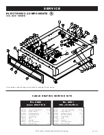
Page 25: ...Insulation Corner 1 foot BU 3105 Shoulder Bushing 12 BU 3106 Cup Bushing 12 ST 2439 Stud 12 NU 2215 Hex Nut 24 SL 3063 Insulating Sleeve 12 TA 3540 Electrical Tape 1 roll No 4881 750 1000 TH II includes CB 3045 Cable Heating Element 134 feet CR 3226 Ring Connector 4 IN 3488 Insulation Corner 1 foot BU 3105 Shoulder Bushing 4 BU 3106 Cup Bushing 4 ST 2439 Stud 4 NU 2215 Hex Nut 8 SL 3063 Insulating...

Page 26: ...4197 1 GU 34197 1 GU 34197 1 21 KNOB THERMOSTAT TIMER KN 26568 3 KN 26568 3 KN 26568 3 22 WHITE PILOT LIGHT 250V LI 3951 2 LI 3951 2 LI 3951 2 WHITE PILOT LIGHT 110V 120V ONLY LI 3027 2 LI 3027 2 LI 3027 2 23 NUT 10 32 NF HEX MS 18 8 S S NU 2215 4 NU 2215 4 NU 2215 4 24 M4 0 7 HEX NUT 18 8 NU 22286 2 NU 22286 2 NU 22286 2 25 NUT HEX 8 32 NU 2296 4 NU 2296 4 NU 2296 4 26 CONTROL PANEL BEZEL PE 2656...

Page 27: ...TH II INSTALLATION OPERATION SERVICE MANUAL PG 25 ...

Page 28: ...PG 26 TH II INSTALLATION OPERATION SERVICE MANUAL ...

Page 29: ...TH II INSTALLATION OPERATION SERVICE MANUAL PG 27 ...

Page 30: ...PG 28 TH II INSTALLATION OPERATION SERVICE MANUAL ...

Page 31: ...TH II INSTALLATION OPERATION SERVICE MANUAL PG 29 ...

Page 32: ...PG 30 TH II INSTALLATION OPERATION SERVICE MANUAL ...

Page 33: ...warranty claim must be asserted during the applicable warranty period This warranty is not transferable THIS WARRANTY DOES NOT APPLY TO 1 Calibration 2 Replacement of light bulbs and or the replacement of display case glass due to damage of any kind 3 Equipment damage caused by accident shipping improper installation or alteration 4 Equipment used under conditions of abuse misuse carelessness or a...

Reviews: