background image

D000161-00 Rev. C


33 

 
To Re-attach the enclosure:


1.  It is easiest to attach the back of the enclosure 

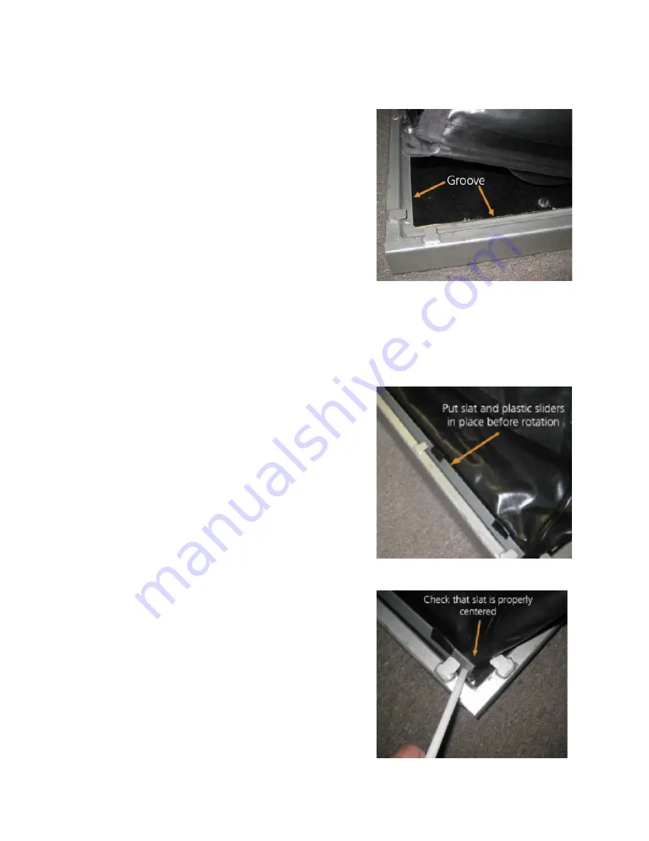
first and follow with the sides.  Place the bottom 
edges of the enclosure in the small groove 
(Figure 26) between the outer edge of the wood 
and the inside of the metal base.  You will 
notice that on the bottom edge of the enclosure 
there is a cylindrical plastic rod that is sewn in 
the enclosure and fits in the groove. 
 

2.  Place the bottom edge of the metal slats on the 

enclosure side of the plastic rods located in the 
hem of the enclosure.  The rod should be 
trapped between the slat and the outer frame.  
Take the plastic sliders and place them on the 
slat.  You will notice that the sliders are tapered on one end.  This is the side that should 
be facing the metal tab.  The slat will be angled toward the enclosure.  Using your 
hands, push down on the metal slat (pushing on the plastic sliders will be more 
comfortable) to clear the metal tabs, then rotate the top edge of the slat outwards, 
capturing the slat under the metal tabs. 


Figure 27 shows the metal slat set in place. Plastic 
sliders have been attached and the slat is ready to be 
pushed down and rotated into place. 


When you place a slat, ensure that it is centered 
properly with regard to the metal tabs as shown in 
Figure 28.  This is the rear slat, and it has an equal 
overhang on each end tab. 


Figure 26 

Figure 27 

Figure 28 

Summary of Contents for AlterG Anti-Gravity Treadmill Pro 200 Plus

Page 1: ...User Manual AlterG Anti Gravity Treadmill Pro 200 Plus ...

Page 2: ...s or operational procedures that may directly affect the safe operation of the AlterG Anti Gravity Treadmill Read and understand these instructions and statements before operating the AlterG Anti Gravity Treadmill Warning Cautionary statement or operational procedure that may directly affect the safe operation of the treadmill compliant product AlterG and Anti Gravity Treadmill are registered trad...

Page 3: ...al Support Frame 14 Zipping Into the Enclosure 15 Attaching the Safety Lanyard 15 Operating the Software Using the Touch Screen 16 Welcome Screen Figure 9 16 Calibration Screen and Procedure Figure 10 16 Control Screen Figures 11 12 17 Adjusting Treadmill Speed Direction 17 Adjusting Treadmill Grade 18 Adjusting Body Weight Percentage 18 Stopping the Exercise Session 19 Stepping Out of the Anti Gr...

Page 4: ...36 SIZES 36 PERFORMANCE 36 DIMENSIONS 36 RECOMMENDED ROOM DIMENSIONS 36 ENVIRONMENTAL 36 ELECTRICAL RATINGS 36 APPENDIX B EMC STATEMENT 38 APPENDIX C OPTIONS AND ACCESSORIES 42 APPENDIX D TROUBLESHOOTING 43 Repairs 43 Display Computer 43 Air Pressure 43 Treadmill 43 Leaks 44 System Errors 44 APPENDIX E WARRANTY INFORMATION 45 ...

Page 5: ...y it is recommended that a request for service be made to AlterG Inc The Anti Gravity Treadmill or any of its parts should only be repaired in accordance with instructions provided by AlterG Inc authorized representatives of AlterG Inc or by AlterG Inc trained personnel The Anti Gravity Treadmill must not be altered without the prior written approval of the AlterG Inc Quality Assurance Department ...

Page 6: ...rmation list is below AlterG Headquarters 48438 Milmont Drive Fremont CA 94538 510 270 5900 www alterg com Service and Support 48438 Milmont Drive Fremont CA 94538 510 270 5369 support alterg com AlterG Europe Ltd The Mill Horton Rd Stanwell Moor Staines Middlesex TW19 6BJ Mon Fri 9am 5pm GMT Phone 44 02036514293 Mobile 44 07733179187 Fax 44 01753682088 support alterg com ...

Page 7: ...D000161 00 Rev C 7 ...

Page 8: ...se electrical disturbances which can interfere with pacemaker function Always unplug the Anti Gravity Treadmill before cleaning or servicing Do not soak any part of the Anti Gravity Treadmill with liquid during cleaning use a sprayer or damp cloth Keep all liquids away from electric components Always unplug the machine before cleaning and maintenance Service should be performed by an authorized te...

Page 9: ... other items near the screens which could get sucked in or block air movement Keep hands away from the enclosure and frame structure during inflation to avoid pinching Keep hands away from all moving parts Do not exceed the maximum user s weight of 400 pounds 182 kgs Care should be taken when entering or exiting the Anti Gravity Treadmill Never enter the Anti Gravity Treadmill while the treadmill ...

Page 10: ...ing Up and Cooling Down It is important to gradually warm up and cool down prior to and at the end of each work out Always try to incorporate a series of basic stretches before and after each workout Stretching encourages the necessary flexibility to help prevent sore muscles and injury during daily activities Do not abruptly end your exercise session on the Anti Gravity Treadmill Always restore y...

Page 11: ...ding Requirements The Anti Gravity Treadmill must be grounded electrically If there is an electrical malfunction grounding provides a path of least resistance for electric current to reduce the risk of electric shock The Anti Gravity Treadmill power cord includes a grounded plug This plug must be plugged into an appropriate receptacle NEMA L6 30R that is properly installed and grounded in accordan...

Page 12: ...n and user access Also check ceiling height to ensure users won t hit their heads The Anti Gravity Treadmill surface is 15 0 38m off the floor when level and can be higher when the subject is running on a grade An 8 foot 2 4m ceiling may be too low for taller users Transporting Your AlterG Anti Gravity Treadmill Contact AlterG if you plan on moving your Anti Gravity Treadmill Damage sustained by i...

Page 13: ...e compression shorts that ensure an airtight seal in the enclosure It is recommended that you put the shorts on before you step into the machine Once you are in the Anti Gravity Treadmill the seal is completed by zipping the shorts and the enclosure together The zipper provides a means of quickly attaching and detaching yourself from the enclosure simplifies hygiene and provides for a custom fit f...

Page 14: ...he support frame at a height that places the zipper at your iliac crest the top outer edge of your pelvic bone felt just below waist level on either side of your body For additional trunk support the frame can be set higher See Figure 3 With the frame at the correct height push it into the slots of the height adjusters in the front and rear Figure 4 of the machine Make sure it is at the same heigh...

Page 15: ...Treadmill The zipper should be started at the front and center of your body figure 6 and zipped counter clockwise all the way around until it returns to overlap in the front Make sure that the zipper is completely closed Attaching the Safety Lanyard It is essential that you always use the magnetic safety lanyard supplied with the machine Clip one end of the lanyard to your shirt at waist level Fig...

Page 16: ...IT at this time until you have read this entire manual or seek appropriate instruction from a qualified user By selecting the Start Session button you acknowledge having read and understood this manual and you will be taken the start session screen Calibration Screen and Procedure Figure 10 After you choose Start Session the calibration screen will be displayed The calibration routine provides cri...

Page 17: ...h of the exercise session Distance Distance in miles or kilometers Heart Rate Heart rate in beats per minute Calories Estimate calories burned during the session Pace Minutes to run a mile or kilometer Adjusting Treadmill Speed Direction Treadmill speed is expressed as a numerical value in miles per hour or kilometers per hour There are arrow controls that allow the speed to be increased or decrea...

Page 18: ... in a reverse direction forcing you to walk backwards The speed display will show a negative number Continuing to press the down arrow control will increase your backwards walking speed and the speed reading will become increasingly negative Pressing the up arrow speed control will slow your backwards walking speed until you reach zero mph at which time the treadmill will stop Check the specificat...

Page 19: ...e chance to resume your workout 2 If you experience discomfort while exercising you can immediately pull on the emergency stop lanyard and displace the magnet from its control panel position This puts the treadmill in freewheel mode and maintains enclosure pressure If you stop the treadmill in this manner remember to step in place to avoid becoming light headed When you End the screen of figure 14...

Page 20: ...ep Stand next to the treadmill and install the oval support bar in the vertical height adjusters and close the safety latches Follow these steps to access the creep control adjustments 1 Double tap on the man s right fist 2 Enter code 5369 Notice the up and down arrows labeled CREEP CONTROL on the screen of figure 16 These arrows allow the user to adjust the belt so it no longer creeps when the tr...

Page 21: ...e receiver within the Anti Gravity Treadmill display 1 Sensor Transmitter The Sensor Transmitter is worn just below the chest and at the top of the abdomen directly on bare skin not over clothing The transmitter should be centered below the pectoral muscles Once the strap is secured pull it away from the chest by stretching the band and moisten the conductive electrode strips with plain water The ...

Page 22: ... used inside the range of any one receiver as the receiver may pick up several signals simultaneously causing an inaccurate readout Workout Programmer Reference www alterg com workout programmer Stride Smart Reference www alterg com user resources ...

Page 23: ...forward completely into the front and back of the height adjusters Always secure the support frame in position by closing and securing the red latches Figure 18 Be aware that you can use this frame to support yourself in case you fall or need to jump off to the sides of the treadmill for some reason Safety Lanyard Magnetic Stop It is essential that you always use the magnetic safety lanyard suppli...

Page 24: ...de information on the operation of the Anti Gravity Treadmill and should be followed for a safe and enjoy able exercise experience Should any of the labels become damaged and unreadable immediately contact AlterG for replacements The location of the labels are indicated in Figure 19 Refer to this diagram to locate the label being described Figure 19 ...

Page 25: ...latches used to secure the oval support frame into the vertical height adjusters For your safety it is critical that you close and lock the latches after installing the oval support bar and before exercising The latches should always be closed when the fabric enclosure is inflated Never open these latches during exercise or during calibration when the enclosure is pressurized Label 4 The emergency...

Page 26: ... position on the console should you fall The treadmill will stop in response to removal of the safety magnet This label is located on the lower right corner of the tubular frame surrounding the touch screen and console Label 6 The oval support frame must be secured in the vertical height adjusters and the safety latches must be closed before exercising This label is affixed at the front of the ova...

Page 27: ... voltage requirements Label 9 This label is located within the structure of the Anti Gravity Treadmill and indicates a high volt age is present in that location If you see this label do not get close to or disassemble any of the components to which it is attached Because the high voltage can cause serious injury or death only a qualified AlterG service technician should attempt any repairs ...

Page 28: ...leach solution Follow CDC recommended procedures for decontamination when shorts become exposed to human waste or blood or when high risk patients or high risk microbial contamination is involved Disposal of the shorts following exposure to waste blood or highly contagious microorganisms or when patients at high risk for infection are involved is recommended Direct exposure of the shorts to solid ...

Page 29: ...d plastic surfaces Also do not soak any surface with a liquid as the sensitive electronics can be damaged or pose an electrical hazard Daily 1 Inspect and remove any loose debris from the interior of the enclosure 2 Check for abnormal operation a Ensure that there are no unusual performance characteristics such as i i Unusual sounds from the treadmill air blower or enclosure such as hissing of air...

Page 30: ...rG immediately IMAR is a trademark of IMAR Products LLC Manassas VA Height Adjusters Latch Mechanism The height adjusters function as an essential safety mechanism in the event that a user falls It is of utmost importance that they are checked before each use Make sure they are not loose or cracked in any way and the oval shaped support frame fits fully into them Check to make sure the notches are...

Page 31: ...black plastic sliders that slide under metal tabs which overhang to the inside of the base frame Follow these steps to remove the enclosure Figure 20 If you look closely at this photo you will see the thin metal strip trapped under metal tabs welded to the main frame The strips hold the enclosure to the base 1 Before you do anything turn off and unplug the Anti Gravity Treadmill 2 Use the plastic ...

Page 32: ...bably don t need to remove both the front and back to clean the entire machine Removing one end and both sides should be sufficient Typically it is best to leave the front of the enclosure attached to the frame In Figure 24 the enclosure has been released on both sides and the back The front of the enclosure remains attached You can suspend the enclosure for better access by placing the oval suppo...

Page 33: ... the outer frame Take the plastic sliders and place them on the slat You will notice that the sliders are tapered on one end This is the side that should be facing the metal tab The slat will be angled toward the enclosure Using your hands push down on the metal slat pushing on the plastic sliders will be more comfortable to clear the metal tabs then rotate the top edge of the slat outwards captur...

Page 34: ...f the slider These can be quite tight so you might need the plastic tool and a mallet to tap them into place Once again be careful not to slip and cut the enclosure 4 Repeat steps 1 3 for each side of the enclosure that you have removed 5 It is preferable that you perform any maintenance where you have to remove the enclosure at the end of the day This will give the foam that forms the airtight se...

Page 35: ...D000161 00 Rev C 35 APPENDICES A Specifications B Options and Accessories C Troubleshooting D Warranty ...

Page 36: ... Forward 0 18 miles per hour 0 29 km hr Reverse 0 10 miles per hour 0 16 km hr Elevation AlterG Anti Gravity Treadmill Pro 200 0 15 grade DIMENSIONS Length 94 inches 240 cm Width 40 inches 102 cm Height Small 72 183 cm Medium 75 191 cm Large 78 5 200 cm Weight 1000 pounds 455 kg approximately RECOMMENDED ROOM DIMENSIONS Provide a footprint at least 12ft long by 8 ft wide for adequate spacing aroun...

Page 37: ...romised Locate AlterG Anti Gravity Treadmill within 8ft of the electrical outlet Electrical Connection 30 ampere circuit NEMA L6 30R receptacle International Configuration The appropriate plug should be attached to the power cord of the AlterG Anti Gravity Treadmill using the following wire connection scheme Blue Conductor Neutral Brown Conductor Line Ground Conductor Green Yellow ...

Page 38: ... 0 8 5 56 5 0 7 32 0 6 3 156 5 23 3 40 0 16 7 44 5 1 3 32 0 9 5 30 8 28 4 40 0 11 6 48 0 0 6 32 0 11 8 40 375 36 6 40 0 3 4 59 5 0 6 32 0 8 5 43 96 31 5 40 0 8 5 55 7 0 7 32 0 7 1 49 97 38 1 40 0 1 9 64 6 0 7 32 0 4 8 51 12 36 8 40 0 3 2 63 4 0 7 32 0 4 7 60 0 29 7 40 0 10 3 57 1 0 8 32 0 3 9 64 01 27 5 40 0 12 5 53 8 0 8 32 0 4 9 79 15 29 4 40 0 10 6 52 8 0 9 32 0 7 7 105 1 25 9 40 0 14 1 51 1 1 ...

Page 39: ... short interruptions and voltage variations on power supply input lines IEC 61000 4 11 5 UT 95 dip in UT for 0 5 cycle 40 UT 60 dip in UT for 5 cycles 70 UT 30 dip in UT for 25 cycles 5 UT 95 dip in UT for 5 sec 5 UT 95 dip in UT for 0 5 cycle 40 UT 60 dip in UT for 5 cycles 70 UT 30 dip in UT for 25 cycles 5 UT 95 dip in UT for 5 sec Mains power quality should be that of a typical commercial or h...

Page 40: ...tion distance in meters m Field strengths from fixed RF transmitters as determined by an electromagnetic site surveya should be less than the compliance level in each frequency range b Interference may occur in the vicinity of equipment marked with the following symbol NOTE 1 At 80 MHz and 800MHz the higher frequency range applies NOTE 2 These guidelines may not apply in all situations Electromagn...

Page 41: ...mum output power of transmitter W Separation distance according to frequency of transmitter m 150 kHz to 80 MHz d 3 5 V1 P 80 MHz to 800 MHz d 3 5 E1 P 800 mHz to 2 5 GHz d 7 E1 P 0 01 0 12 0 12 0 23 1 0 37 0 37 0 74 1 1 17 1 17 2 33 10 3 69 3 69 7 39 100 11 67 11 67 23 33 For transmitters rated at a maximum output power not listed above the recommended separation distance d in meters m can be est...

Page 42: ...D000161 00 Rev C 42 APPENDIX C OPTIONS AND ACCESSORIES Please visit the AlterG Store http store alter g com or contact your AlterG Sales representative for pricing and ordering ...

Page 43: ...he On button If nothing happens check to make sure the machine is plugged in If it is check the circuit breaker If this is ok and the display is still blank contact AlterG there may be a loose connection somewhere Air Pressure If you are at a place in the user interface where the blower should be turned on calibration or control screen where you can adjust speed incline and weight but isn t do the...

Page 44: ...ersists AlterG service should be contacted and the circumstances under which the error occurs and the Diagnostic Code should be relayed to the technician Although certainly not common the two diagnostic descriptions you are most likely to see are the Woodway Timed Out and the Micro Timed Out error codes System Fatal Error Woodway Timed Out The treadmill operates in a timer configuration If the tre...

Page 45: ...et speed Click restart black screen command prompt click the x at the top right hand corner brought back to home screen to begin new session Facility Settings Code 5900 Input facility information adjust camera settings reset cameras Facility Settings Code 5369 Adjust treadmill belt creep Shut Down No soft shut down button Instruct users to push hard button on monitor Speed change Treadmill will sl...

Page 46: ...This allows the user to do a cool down after their workout is complete Workout Programmer Pre programmed Select Workout goes to pre programmed workouts Workout Programmer Personalized USB Insert USB key to select personalized workouts Click Source to switch between USB and pre programmed ...

Page 47: ...ranties are only available within one 1 year of the purchase date of the product and prices are subject to change During the Warranty period or Extended Warranty period AlterG or its authorized service technician will diagnose and repair your AlterG Anti Gravity Treadmill including parts and labor The service can range from phone calls and emails to onsite service visits as necessary If you choose...

Reviews: