Commissioning
Instruction manual 91/104 V9.2
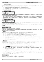
This parameter sets the speed (and direction) of the motor during JOG operation. When using “Fixed " jog mode, you can change the
direction of the motor by reversing the sign of this parameter. Instead, when using a waveform to move the motor, this parameter is
taken as “absolute value ", therefore without a sign.
The maximum absolute value of this parameter is however limited to the maximum motor speed set in the parameter "Maximum
speed“ (see page 37).
Motor overtemp
Set of parameters to set the signal or block of the drive in case of overheating of the motor. For further explanations see paragraph
"Motor temperature“ on page 65.
Signal Mode
With this parameter you set the type of signal you want to do when the motor overheats. The motor temperature control is carried out
with a PTC sensor installed inside the motor. The possible selections are as follows:
•
DIG.OUT ONLY: This is the standard setting that was made to have compatibility with previous versions. In this case, when
the motor PTC contact opens (overheated motor), the drive does NOT DO NOT NULL and continues to operate regularly at
infinite time. On a selectable digital output (see paragraph "Dig.Op. X source“ on page 44) you can send a signal to the CNC
or PLC so that it can make the necessary decisions for this anomaly: stop the machining or continue for a certain time.
•
DRIVE FAULT: By setting this mode the drive can disable the operation and signal the anomaly outside. As soon as the mo-
tor PTC contact opens (overheated motor) the drive causes a signal to appear on the display (see message "Warning!!! Motor
Overtemp.“on page 83) and indicates on a selectable digital output (see section "Dig.Op. X source“ on page 44) the
overheating of the motor, but continues to operate regularly. From that moment the CNC or PLC must decide whether to stop
the machine or continue the machining; After the time set in the “Drive FLT delay " parameter, the drive locks and disables
the motor, signaling the alarm "Motor Overtemperature“ and bringing to the logical level "0" the digital output "DOK ".
Drive FLT delay
Minimum Maximum Units of measure
0
120
Minutes
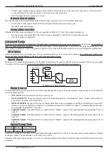
This parameter sets the delay with which the drive crashes to protect the motor’s overheating. This delay starts when the PTC sensor
installed in the motor opens; when the delay is over, the drive will disable and the motor stops by inertia. The display of the drive dis-
plays the alarm "Motor Overtemperature“ and the digital output "DOK" is brought to the logical level "0 ".
Summing block
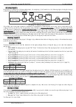
Group of parameters to verify the value of inputs and outputs from the summation function (see paragraph 5.6.14 on page 75).
Input 1
Minimum Maximum Units of measure
-100,00
+100,00
%
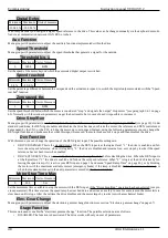
Percentage value of input 1 of the summing block. This number
follows the associated analog input signal via the appropriate I/O
analog input configuration menu.
Input 2
Minimum Maximum Units of measure
-100,00
+100,00
%
Percentage value of input 2 of the summing block. This number
follows the associated analog input signal via the appropriate I/O
analog input configuration menu.
Input 3
Minimum Maximum Units of measure
-100,00
+100,00
%
Percentage value of input 3 of the summing block. This number follows the associated analog input signal via the appropriate I/O ana-
log input configuration menu.
Input 4
Minimum Maximum Units of measure
-100,00
+100,00
%
Percentage value of input 4 of the summing block. This number follows the associated analog input signal via the appropriate I/O ana-
log input configuration menu.
52
Alter Elettronica s.r.l.


