Instruction manual 91/104 V9.2
Commissioning
5. Analogue reference position:
when you need more than 4 positions or if you need to change the position in real time you can
use an analog input set to send its signal to “position 0 ". In this way, by changing the analog signal you can change the posi -
tion set at any time, provided you have selected the use of “position 0 " as the current position reference.
To check the actual position that the motor has reached, you can read the position indicated by the parameter "Current Position“ (see
page 51).
NOTE:
In case of use of a multipolar resolver (from 4 poles upward), the position is NOT the actual position of the motor shaft,
but that of the sinusoid currently generated by the resolver. For example, if a 6-pole resolver is used, it generates 3 complete
sinusoids for each revolution of the transducer; so for every revolution of the motor shaft you get 3 times the same position. In
practice in the case of a 6-pole resolver (for example), every 120° of the motor shaft will get the same position; From this you can
deduce that it is not recommended the use of multipolar resolver if you want to position the motor exactly in the revolution.
5.6.14 Summing block
5.6.14.1 Generality
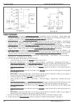
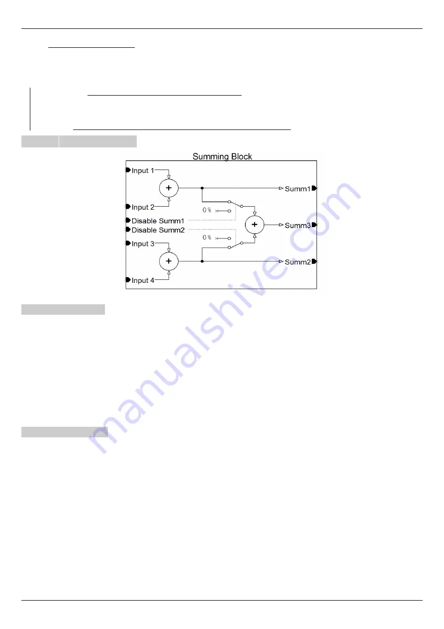
This function is used to add 4 analog signals to groups of two, and to output the 3 sum values. With reference to drawing 23 we can
find:
•
Input 1
÷ 4
: It is the input signals to the block that come from the sources that have been selected. These values are added
together as shown in the drawing.
•
Disable Summ1
: it can be controlled by a digital input to disable the sending of the sum 1 result to the summation 3 (as can
be seen from the drawing). In rest condition (or with no associated digital input) the sum 1 value is sent to the summation 3.
•
Disable Summ2: it can be controlled by a digital input to disable the sending of the sum 2 result to the summation 3 (as can
be seen from the drawing). In rest condition (or with no associated digital input) the sum 2 value is sent to the summation 3.
•
Summ1 ÷ 3
: They are the output signals from the relative summaries, as can be seen from the drawing, and can be associated
with analog outputs or with the ramp input to generate the speed reference to the motor (see paragraph "Ramp Source“ on
page 47).
5.6.14.2 Calibration
This function does not need calibration. To use it you have to set the analog inputs that will have to provide the signals in the inputs of
the summaries from the configuration menu "I/O Configure → Analog Inputs" and from the selection menu of the destination of the
desired input go to select the entry "Inp.X SumBlock" (see paragraph "An.Inp. X dest“ on page 41).
Each analog input has an Offset and Gain parameter that can be used to adapt the signal to the summing block as needed.
The sum results (Summ1, Summ2, Summ3) can be sent to analog outputs or to the input of the speed ramp to control the motor.
If you need to reset an external command reference, you can use one of the “DisableSumm " inputs by associating them with a digital
input.
Alter Elettronica s.r.l.
75
Drawing 28: Summing block

