Commissioning
Instruction manual 91/104 V9.2
•
Check STAGE 1
: the digital input monitors the effective closing of the contactor of the connections of stage 1 (i.e. Quick
Gamma).
•
Posit. Enable
: The digital input (standard on DI4) enables motor positioning at the selected position (see section
"Positioner“ on page 74).
•
Posit. BIT 0
: The digital input sets the "Bit 0" of the position selector to be reached with the positioner (see section
"Positioner“ on page 74).
•
Posit. BIT 1
: The digital input sets the "Bit 1" of the position selector to be reached with the positioner (see section
"Positioner“ on page 74).
•
Gain Selection:
the digital input (standard on DI3) switches the following parameters:
━
Analog input gain AI1 (see paragraph "An.Inp. X Gain“ on page 41).
━
Proportional gain speed loop (see paragraph PID Speed Loop on page 53).
━
Integral gain speed loop (see paragraph PID Speed Loop on page 53).
If the inversion of sign has not been activated, the meaning is as follows:
━
0V: GAIN 1 selection (in the parameters written just above).
━
24V: GAIN 2 selection (in the parameters written just above).
•
Jog Enable
: digital input (standard on DI2) enables motor jog operation. For the explanation of this function, please refer to
the appropriate paragraph "JOG function“ on page 71.
•
Spindle Lock
: the digital input enables the “spindle shaft locking " function. See paragraph 5.6.12 on page 73.
•
Disable Summ1
: The digital input controls the input of “deactivation sum 1 " into the summing block (see paragraph 5.6.14
on page 75).
•
Disable Summ2
: The digital input controls the input of “deactivation sum 2 " into the summing block (see paragraph 5.6.14
on page 75).
NOTE:
If two or more different digital inputs are accidentally assigned to the same function, the one that has priority over the oth-
ers is the one with the highest number (e.g.: input DI3 has priority over input DI1).
Dig.Inp. X Sign
With this parameter you can select whether to reverse the read logical state from the associated digital input or to leave it as originally.
The possible selections are:
•
NORMAL: The “Value " signal indicates exactly the logical state of the associated digital input.
•
REVERSE: The “Value " signal is logically reversed with respect to the logical state of the associated digital input.
See Drawing 17 for more clarity.
Dig.Inp. X Value
Read-only parameter that indicates the logical state outgoing from the compensation block of the digital input. See Drawing 17 for
more clarity.
Digital outputs
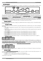
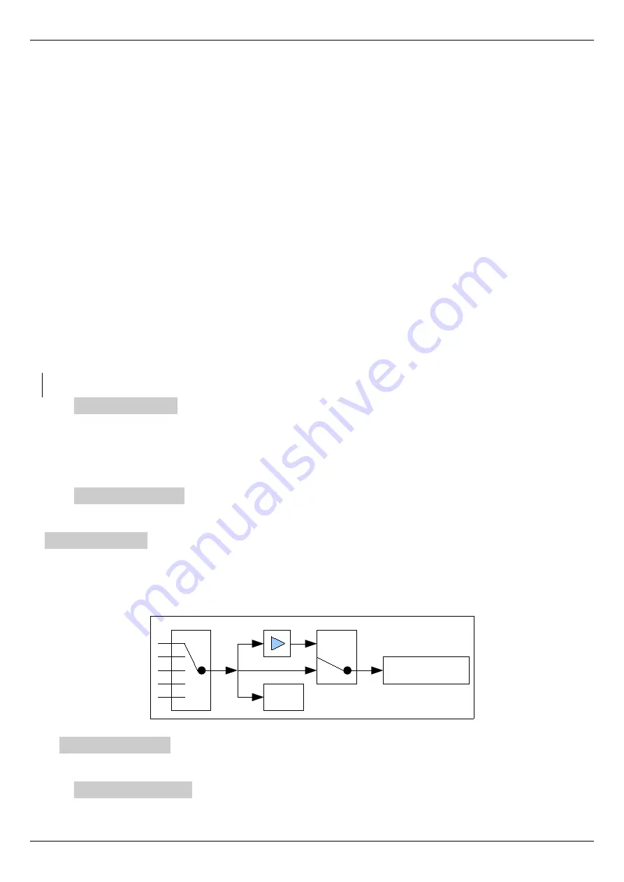
Menu group to configure and calibrate digital outputs. For simplicity it is advisable to see the following figure showing the internal
calibration structure of a generic digital output.
The logical status on the terminals of the digital output can be controlled by several selectable sources. The calibration block of the di -
gital output after reading the value of the selected source allows you to select whether to send out the same selected logical state or to
reverse it logically before transferring it to the output.
Digital Output X
Menu group to configure the digital output X. Changes to the calibration values made in this group, act only on the indicated digital
output and not on the others.
Dig.Op. X source
Parameter that allows you to select the source of the digital output. Using the keys you can select the source from among these:
•
NOT USED: the digital output is not used and the “Value " is always FALSE.
44
Alter Elettronica s.r.l.
Drawing 18 Digital Output Structure
Digital Output X
False/True → 0/+24V
VALUE
REVERSE
NORM
SIGN
Source selector


