1
Altai Technologies Ltd. All rights reserved
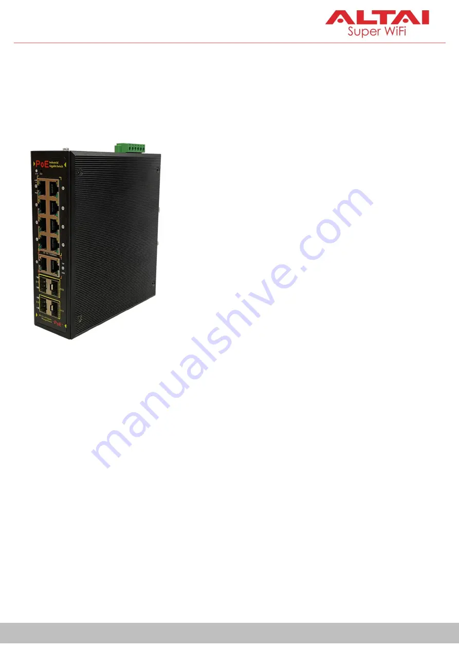
Quick Setup Guide
ALTAI MIS200P Industrial 14-Gigabit-Port Managed PoE Switch
______________________________________________
Version 1.1
Page 1: ...1 Altai Technologies Ltd All rights reserved Quick Setup Guide ALTAI MIS200P Industrial 14 Gigabit Port Managed PoE Switch ______________________________________________ Quick Setup Guide Version 1 1...
Page 2: ...ou for purchasing the Altai MIS200P product This guide provides instructions to install the product and set it up with minimal effort 2 Package Content MIS200P Main Unit x 1 pc DC Terminal Block Conne...
Page 3: ...warehouse and container port The switch supports 802 3af at Power over Ethernet a system to transmit electrical power up to 30 watts along with data to remote devices over standard twisted pair Ether...
Page 4: ...DC redundant power input with polarity reverse protection DIN rail mount 4 kV power and data port surge protection 8 kV Ethernet ESD protection Support ERPS redundant ring technology with recovery ti...
Page 5: ...ned to work with Altai APs A typical use case is as an access switch for an outdoor site where multiple APs and other devices are co located Power Data over Ethernet Cable to 802 3af at PD Data over E...
Page 6: ...and anti vibration capabilities the switch can readily be used in an RTG or AGV for connecting a Wi Fi CPE such as A2x and VX200 to VMT Vehicle Mounted Terminal and Camera 18 32V DC Quay Crane AGV RTG...
Page 7: ...7 Altai Technologies Ltd All rights reserved Quick Setup Guide 6 Hardware Overview Physical Dimensions Front Panel Back Panel 165 mm A C E F G B I D H J...
Page 8: ...ed twisted pair of Ethernet cables for the connection Cable run can be up to 100 meters Below is the table about the cable specifications Cable Categories Supported Ethernet Signal Max Length Connecto...
Page 9: ...T568B specification see Appendix C and D Each port comes with two LEDs Link and PoE to show its working status For details see Section F and G respectively B Copper Ports G9 G10 2 extra ports of 10 10...
Page 10: ...n plug in and out the transceiver to from the SFP slot without having to power down the switch Before making the connection make sure the SFP transceivers are of the same media type on both sides e g...
Page 11: ...er is operating correctly To remove the SFP transceiver follow the steps below 1 Remove the fiber optic cable gently from the SFP transceiver 2 Pull the bail latch of the transceiver forward 3 Grasp t...
Page 12: ...ng System abnormal or failure F Link Status Indicator of PoE Port Indicator Color State Description LINK Amber On Link connected Blinking Data transmitting receiving Off Link disconnected or failure G...
Page 13: ...h Off Link disconnected or failure I Link Status Indicator of SFP Slot Indicator Color State Description 11 14 Green On Link connected Blinking Data transmitting receiving Off Link disconnected or fai...
Page 14: ...ded ground screw Connect the other end of ground wire to a reliable earth ground point at site M Console Port Used with a RJ 45 to RS232 DB9 console cable for local access and management To make the c...
Page 15: ...h strong electromagnetic interference Installation To mount the MIS200P unit on the rail follow the steps below 1 Insert the upper bracket lip into the DIN rail 2 Pull the buckle down to snap the brac...
Page 16: ...se 18 32V DC power input Size of power wires 12 18 AWG Procedures When performing the procedures like inserting the wires or tightening the wire clamp screws make sure the power is OFF to prevent from...
Page 17: ...e the flat blade screwdriver to lock the terminal block to the MIS200P unit in place 4 Connect the positive and negative DC wires to a power source s 5 Turn on the power source s When the PWR LED ligh...
Page 18: ...tch Below are the industrial AC DC power supply models which are applicable to the MIS200P switch Part Number Description SD PE 0001 MW Industrial power supply 100 240 VAC in 48 VDC 2 5A out 120W DIN...
Page 19: ...lock to indicate the power fault event Insert two wires size 12 18 AWG into the relay contacts When power fault occurs the two wires attached to the relay contacts form an open circuit If the switch i...
Page 20: ...in connection with the unit Click it and then click Properties 2 Under the Networking tab select Internet Protocol Version 4 TCP IPv4 in the list box This connection uses the following items and then...
Page 21: ...in the address bar and hit Enter 2 Login box will pop up Enter the username and password By default the credentials are Username admin Password admin 3 If successful you will be brought to the follow...
Page 22: ...SSH 1 Use a terminal emulator such as PuTTY or Windows 10 Built in OpenSSH client or macOS built in terminal program 2 Login to the switch with the correct username password and port number By defaul...
Page 23: ...r 10 100BASE T Signal 1000BASE T Signal 1 White Orange TD with PoE Input BI_DA with PoE Input 2 Orange TD with PoE Input BI_DA with PoE Input 3 White Green RD with PoE Input BI_DB with PoE Input 4 Blu...
Page 24: ...00BASE T Signal 1000BASE T Signal 1 White Green TD with PoE Input BI_DA with PoE Input 2 Green TD with PoE Input BI_DA with PoE Input 3 White Orange RD with PoE Input BI_DB with PoE Input 4 Blue Unuse...
Page 25: ...ologies Ltd All rights reserved Quick Setup Guide Appendix C Pin Assignments and Wiring for a Straight Through Cable using T568B Standard 1 2 3 4 5 6 7 8 1 2 3 4 5 6 7 8 1 2 3 4 5 6 7 8 1 2 3 4 5 6 7...
Page 26: ...echnologies Ltd All rights reserved Quick Setup Guide Appendix D Pin Assignments and Wiring for a Crossover Cable using T568B Standard 1 2 3 4 5 6 7 8 1 2 3 4 5 6 7 8 1 2 3 4 5 6 7 8 1 2 3 4 5 6 7 8 E...
Page 27: ...for any inaccuracies in this document or for any obligation to update information in this document This document is provided for information purposes only Altai Technologies reserves the right to chan...