background image

508145-01B

Page 26 of 36

Issue 2108

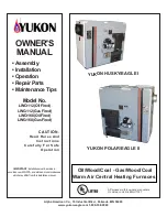
THERMOSTAT CONNECTIONS (TB1)

1/4” QUICK CONNECT TERMINALS

DS = DEHUMIDIFICATION SIGNAL

W2 = HEAT DEMAND FROM 2ND STAGE T/STAT

W1 = HEAT DEMAND FROM 1ST STAGE T/STAT

R = CLASS 2 VOLTAGE TO THERMOSTAT

G = MANUAL FAN FROM T'STAT

C = THERMOSTAT SIGNAL GROUND CONNECTED TO

TRANSFORMER  GRD (TR) & CHASIS GROUND (GRD)

Y1 = THERMOSTAT 1ST STAGE COOL SIGNAL
Y2 = THERMOSTAT 2ND STAGE COOL SIGNAL

O = THERMOSTAT SIGNAL TO HEAT PUMP

REVERSING VA LVE

L = NOT USED

DH = NOT USED

HUM = UNPOWERED NORMALLY OPEN (DRY) CONTACTS

LI = 120 VAC INPUT TO CONTROL

ACC = 120 VAC OUTPUT TO OPTIONAL ACCESSORY

NEUTRALS  = 120 VAC NEUTRAL

3/16” QUICK CONNECT TERMINALS

FLAME SENSE SIGNAL

HI Cool 24VAC

HI HEAT 24VAC

LO COOL 24VAC

LO HEAT 24VAC

PARK

PARK

COMMON 24VAC

Flame Sense

S4 DIP Switches

24VAC Indoor

Blower Terminals

HUM

ACC

Ignitor and Combustion

Air Inducer

Neutrals

On Board Links

LED

Diagnostic Push

Button

Figure 23. Integrated Control

Summary of Contents for Home BG802DFE

Page 1: ...or the gas supplier WARNING As with any mechanical equipment personal injury can result from contact with sharp sheet metal edges Be careful when you handle this equipment CAUTION Table of Contents B...

Page 2: ...A B C D 3 4 19 27 3 4 705 19 1 4 489 6 5 8 168 Right 7 1 8 181 Left 5 3 8 137 Right 2 3 16 56 Left 33 838 AIR FLOW 3 4 19 19 7 16 494 9 16 14 B Supply Air Supply Air 9 16 14 9 16 14 3 1 8 79 9 16 14...

Page 3: ...s Arrangement Figure 1 Control Box includes integrated control transformer and door switch Secondary Limit Internal Flue Pipe Assembly Gas Valve Burner Box Assembly Combustion Air Inducer Indoor Blowe...

Page 4: ...ional Fuel Gas Code ANSI Z223 1 The National Fuel Gas Code is available from the following address American National Standards Institute Inc 11 West 42nd Street New York NY 10036 Clearances Adequate c...

Page 5: ...O NOT USE THE UNIT FOR CONSTRUCTION HEAT UNLESS ALL OF THE FOLLOWING CRITERIA ARE MET a Furnace must be in its final location The vent system must be permanently installed per these installation instr...

Page 6: ...situation In the absence of local codes concerning air for combustion and ventilation use the guidelines and procedures in this section to install these furnaces to ensure efficient and safe operation...

Page 7: ...a space categorized as unconfined air can be brought in by providing two permanent openings between the two spaces Each opening must have a minimum free area of 1 square inch 645 mm2 per 1 000 Btu 29...

Page 8: ...ve a free area of at least 1 square inch per 4 000 Btu 645 mm per 1 17 kW per hour of the total input rating of all other equipment in the enclosure Setting Equipment Do not install the furnace on its...

Page 9: ...R PLENUM OPENING Cabinet Width Front to Rear Side to Side in mm in mm A 14 1 2 19 3 4 502 13 1 4 337 B 17 1 2 19 3 4 502 16 1 4 413 NOTE Floor opening dimensions listed are 1 4 inch 6 mm larger than t...

Page 10: ...al screws from the outside In this case make plenum with a removable front and install screws from the inside see Figure 12 5 Make certain that an adequate seal is made Cabinet Width Front to Rear Sid...

Page 11: ...ingle wall vent is used on 14 1 2 in cabinets or 2 in if a single wall vent is used on 17 1 2 in cabinets The furnace may be installed on a combustible wood floor if an optional additive base is insta...

Page 12: ...as vent Unlined masonry chimneys are prohibited See Figure 17 and Figure 18 for common venting Venting Using a Masonry Chimney The following additional requirements apply when a lined masonry chimney...

Page 13: ...himney no other appliance can be vented into the chimney The outer wall of type B1 vent pipe must not be exposed to flue products A type B1 vent or masonry chimney liner shall terminate above the roof...

Page 14: ...e maximum common vent capacity listed in the common venting tables should be reduced by 20 the equivalent of two 90 elbows 0 80 x maximum common vent capacity The horizontal length of the offset shall...

Page 15: ...49 39 98 51 164 64 247 10 0 0 88 0 175 0 295 0 447 2 12 61 17 118 23 194 26 289 5 23 57 32 113 41 187 52 280 10 30 51 41 104 54 176 67 267 15 0 0 94 0 191 0 327 0 502 2 11 69 15 136 20 226 22 339 5 2...

Page 16: ...220 15 1 21 50 33 89 47 142 64 220 2 22 53 35 96 49 153 66 235 3 24 55 36 102 51 163 68 248 20 1 21 54 33 99 46 157 62 246 2 22 57 34 105 48 167 64 259 3 23 60 35 110 50 176 66 271 30 1 20 62 31 113 4...

Page 17: ...ange hoods and bathroom exhausts so they will operate at maximum speed Do not operate a summer exhaust fan Close fireplace dampers 4 Follow the lighting instructions Turn on the appliance that is bein...

Page 18: ...ittings and furnace rating to avoid excessive pressure drop Table 8 lists recommended pipe sizes for typical applications 3 The gas piping must not run in or through air ducts clothes chutes gas vents...

Page 19: ...te CAUTION The unit is equipped with a field make up box on the left hand side of the cabinet The make up box may be moved to the right side of the furnace to facilitate installation If the make up bo...

Page 20: ...d to one of the provided neutral terminals If a humidifier rated at greater than one amp is connected to this terminal it is necessary to use an external relay Generator Use Voltage Requirements The f...

Page 21: ...508145 01B Issue 2108 Page 21 of 36 070 12 090 16 COMFORT SYNC THERMOSTAT Figure 22 Wiring Diagram...

Page 22: ...d stage heat ON delay OFF 7 minutes ON 12 minutes ON CUT ON BOARD LINK W915 2 STAGE COMPR T STAT FURNACE TERM STRIP OUTDOOR UNIT Not required on all units 1 Heat 2 Cool with t stat with dehumidificati...

Page 23: ...LINK W915 2 STAGE COMPR CUT ON BOARD LINK W914 T STAT FURNACE TERM STRIP OUTDOOR UNIT o Not required on all units 2 Heat 1 Cool with t stat with dehumidification mode OFF CUT ON BOARD LINK W914 T STAT...

Page 24: ...RNACE TERM STRIP HEAT PUMP 67M41 Y H L Y2 D B L Y2 T T outdoor sensor Dual Fuel Two Stage Heat Pump Thermostat w dual fuel capabilities Capable of 2 stage gas heat control OFF CUT ON BOARD LINK W951 H...

Page 25: ...NACE TERM STRIP HEAT PUMP 67M41 Y H L Y2 D B L Y2 T T outdoor sensor Dual Fuel Two Stage Heat Pump Thermostat w dual fuel capabilities Capable of 2 stage gas heat control with dehumidification mode OF...

Page 26: ...GNAL Y2 THERMOSTAT 2ND STAGE COOL SIGNAL O THERMOSTAT SIGNAL TO HEAT PUMP REVERSING VA LVE L NOT USED DH NOT USED HUM UNPOWERED NORMALLY OPEN DRY CONTACTS LI 120 VAC INPUT TO CONTROL ACC 120 VAC OUTPU...

Page 27: ...DIP Switch Settings Switches 3 and 4 Heating Mode Blower Off Delay The blower on delay of 30 seconds is not adjustable The blower off delay time that the blower operates after the heating demand has...

Page 28: ...ore attempting to perform any service or maintenance turn the electrical power to unit OFF at disconnect switch CAUTION BEFORE LIGHTING smell all around the appliance area for gas Be sure to smell nex...

Page 29: ...al 1 cu ft Dial 2 cu ft Dial 070 55 110 136 272 090 41 82 102 204 Natural 1000 btu cu ft LP 2500 btu cu ft Table 13 Furnace should operate at least 5 minutes before checking gas flow Determine time in...

Page 30: ...ure in wg 4 501 7 500 ft Manifold Pressure in wg 7 501 10 000 ft 2 Supply Line Pressure in wg Low Fire High Fire Low Fire High Fire Low Fire High Fire Min Max 070 Natrual 1 7 3 5 1 5 3 2 1 7 3 5 4 5 1...

Page 31: ...peed terminal 7 Resecure blower access panel 8 Turn on electrical power to furnace 9 Recheck temperature rise Heating Sequence of Operation Electronic Ignition The two stage variable speed integrated...

Page 32: ...h does not close the combustion air inducer will switch to high fire After a 15 second pre purge the high fire pressure switch will close and the unit will begin operation on high fire After 10 to 20...

Page 33: ...for gas leaks CAUTION Annual Furnace Maintenance At the beginning of each heating season and to comply with the Blue Summit Limited Warranty your system should be checked as follows 1 Check wiring fo...

Page 34: ...Ignitor Primary limit control Flame rollout switch s Secondary limit Repair Parts List The following repair parts are available through independent Blue Summit dealers When ordering parts include the...

Page 35: ...e in w c Air Volume Watts at Various Blower Speeds High Black Medium High Brown Medium Blue Medium Low Yellow Low Red cfm watts cfm watts cfm watts cfm watts cfm watts 0 10 1700 423 1495 293 1380 233...

Page 36: ...height of eight 8 feet above grade directly in line with the exhaust vent terminal for the horizontally vented gas fueled heating appliance or equipment The sign shall read in print size no less than...

Reviews: