background image


Heatmaster 2


20 

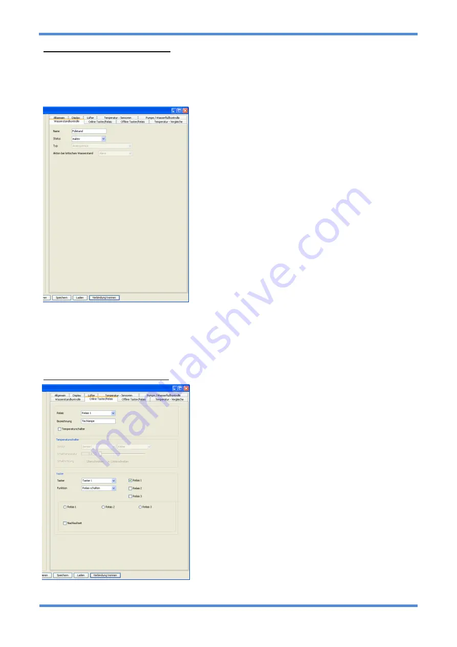
Coolant level control configuration 


Name 

It is possible to set a name for the coolant level sensor. The name may contain up to 255 characters made 
up of letters and numbers. 


Status 

Sets the status of the channel to: Off, not connected or On. 
 

Type 

Here you can choose whether the connected sensor is an 
analogue sensor (which actually determines the coolant level) 
or a floater switch which will only give a signal when a certain 
level is exceeded or undercut. 
 

Action in case of critical coolant level  

Here an action can be set for the case of a critical coolant level. 
Choose from: No action, warning, alarm or emergency 
shutdown. 


Orientation


Set the orientation of the sensor in the reservoir here. When a 
floater switch is used, it is also possible to set whether the 
sensor is “closing” or “opening” 
 

Alarm settings 

With a floater switch the alarm is activated when the switch 
activates. For an analogue sensor it is possible to set a “critical 

level”. If this level is undercut the alarm will be activated.  
 

Calibrate analogue sensor now


Push this button and follow the instructions. The sensor must be removed completely from the coolant and 
then re-installed during the process. This allows the software to determine the conversion factor for the water 
level in percent. 

 
Online button / relay configuration 

The online relay and button control allows highly complex 
adjustments to be made whilst the system is running. To use 
these features it is necessary to connect one or multiple relays 
as well as one or multiple buttons to the Heatmaster 2. These 
items will be available soon as accessories. Please check the 
Alphacool product page for further information regarding 
accessories. Please note that we have refrained from disabling 
settings which are contradictory. Hence it is possible to make 
contradicting switching procedures. The software is 
programmed that in the worst case the procedures will not be 
executed or will be executed with a delay in between. Please 
inform yourself very thoroughly about the options and 
possibilities before configuring a switching procedure. 
 

Switching of a relay via a button 

Set the relay to “manual”. At the “button” option you can now 
choose 

a button by choosing the option “switch relay” and 

marking the according relay next to it. 
 

Switching of a relay for a limited period of time  

If a relay is intended not switch permanently when the button is 
pushed, it is also possible to set a delayed switch-back of the 
relay. The option “switchable via software” can be deactivated. 

If the option is not active, the relay can only be controlled via a button. If the option is activated, the software 

Summary of Contents for Heatmaster 2

Page 1: ...Alphacool International GmbH Heatmaster 2 Operating Manual...

Page 2: ...ation reserved Analog and digital reproduction of any kind except a copy of the end user customer requires the written permission of the Alphacool International Gmbh This manual is written according t...

Page 3: ..._________________________________________________________ 9 PC shut down ________________________________________________________________________ 9 NTC 1 6 temperature sensors ________________________...

Page 4: ...___ 18 Settings____________________________________________________________________________ 18 Temperature values __________________________________________________________________ 19 Pump flow rate s...

Page 5: ..._______________________________________________23 TECHNICAL DATA _____________________________________________________23 DISPOSAL ____________________________________________________________23 APPENDI...

Page 6: ...correctness of this data Regarding the type and extent of the order only the information provided with the order and order confirmation are determining 1 If a defect covered by the warranty occurs yo...

Page 7: ...alled solidly in a free space in the enclosure Please make sure that the USB connector is connected with the correct polarity If the USB cable is connected with wrong polarity both the Mainboard as we...

Page 8: ...age www Alphacool com Socket assignment Overview Power supply The Alphacool Heatmaster 2 is connected to the power supply via a 4 Pin Molex plug just like a HDD or optical drive Both voltage 12V and 5...

Page 9: ...nels for pumps flow sensors aren t necessarily compatible with the according components This means that in some cases it is e g necessary to connect a 3 Pin plug to the pump flow sensor Please check i...

Page 10: ...2 detects these after a reset The setting can also be made manually Water level To this input an analogue coolant level sensor can be connected With this sensor the Heatmaster is able to give a warnin...

Page 11: ...rity may lead to destruction of the Mainboard and or the Alphacool Heatmaster 2 Now connect the power cable 4 Pin plug Be very careful not to damage the other components on the board Now connect the c...

Page 12: ...d with the installation Choose the target folder for the installation Click on Install to proceed Setup_USB will copy the required files For the connection between PC and Alphacool Heatmaster 2 a spec...

Page 13: ...ditions to proceed with the installation Click on Next to proceed Choose the target folder for the installation of the USB driver Click on Next to proceed Click on Install to proceed with the installa...

Page 14: ...ck on Install to implement the hardware The setup will search for connected devices Confirm by clicking OK to complete the installation The driver installation is now complete Click on Finish to close...

Page 15: ...s been installed the software can be installed To start the software setup open the file Setup_HM2 Choose the desired language The installation assistant will start Click on Next to proceed Accept the...

Page 16: ...r 2 software Click on Next to proceed Choose a start menu folder Click on Install to proceed The Heatmaster 2 software is now being installed All settings are now made and the Heatmaster 2 software ha...

Page 17: ...atmaster 2 This is especially important if multiple devices are connected e g in a server or network Temperature unit The temperature can be displayed in C or K The setting made here will be automatic...

Page 18: ...et Fan configuration Here the fan channel for which the settings will be made can be Name It is possible to name every fan channel individually The name may contain up to 255 characters made up of let...

Page 19: ...ible for the Alphacool Heatmaster 2 to maintain the set target temperature This is not an error or reason for reclamation but rather caused by the many possible settings of the Heatmaster 2 as well as...

Page 20: ...to Off not connected or On Type Here the channel can be set to pump or flow rate sensor mode Factor This factor represents how many signals the pump flow rate sensor sends per revolution Normal flow...

Page 21: ...determine the conversion factor for the water level in percent Online button relay configuration The online relay and button control allows highly complex adjustments to be made whilst the system is r...

Page 22: ...stem The only requirement is an active stand by power supply as well as buttons and relays which will be available as accessories soon Please note that we have refrained from disabling settings which...

Page 23: ...nteed that your system will always be protected Especially the automatic reboot feature on some Mainboards may lead to complications with the relay button configuration This greatly depends on the Mai...

Page 24: ...m x 145mm Current draw max 6 3A Fan channel output power max 18W 38w aktiv cooled per channel Overall maximum output power max 75W overall Maximum relay channel power consumption max 5W per relay Disp...

Page 25: ...tion in the world Expansion for analogue adaptor For special fans e g in the laboratory sector it is possible to connect an analogue expansion strip parallel to the existing fan channels This expansio...

Reviews: