030-803-J0 Rev B
Page 24 of 26
1. Shut off the unit and unscrew the front fastener that secures the power module to the shelf.
2. Slide the module 10 cm (4”) out of the shelf and wait two minutes for module capacitors to discharge.
3. Remove the four screws (two each side) that secure the front panel to the module chassis.
4. Slide the front panel out.
5. Disconnect the fan power lead wires (one set per fan) and front panel ribbon cable from the module.
6. Remove the screws that secure the fans to the front panel.
7. Note the direction of airflow and remove the fans (or filters) from the front panel.
8. Install the replacement fans (or filters) following the preceding steps in reverse order.
9.2
MOV Replacement
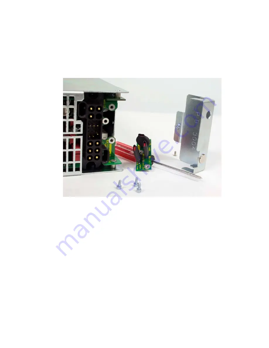
Figure 10–MOV replacement
The MOVs (metal oxide varistor) are used to protect the power modules from power line surges and the surges
caused by lightning strikes. High capacity surges may permanently damage MOVs but they are easily replaced in
the field using the following procedure:
1. Shut off the unit and unscrew the front fastener that secures the power module to the shelf.
2. Slide the module 10 cm (4”) out of the shelf and wait two minutes for module capacitors to discharge.
3. Turn the module around to face the back of the unit and remove the one screw (module bottom toward the
rear) securing the MOV cover.
4. Remove the cover and locate the MOV printed circuit board (PCB).
5. Remove the three screws that secure the MOV PCB.
6. Decontaminate the area and unit with flux remover or a similar cleaning compound. This is to remove any
metallic particles or carbon, which may have been deposited when the MOV failed.
7. Install the replacement MOV PCB following the preceding steps in reverse order.
See Section 1.3. The information is valid at the time of publication. Consult factory for up-to-date ordering information.


