background image


 __________________________________________________________________________________  

Alpha ESS Co., Ltd. 

Page 50 of 59 
 

Your Smart Energy 

Operation 

To  prevent  battery  from  over  discharge,  you  can  set  the  remaining  SOC  of  the  device  in 
“Controlled  Discharge”  mode  by  selecting  “UPS  reserved  capacity”.  It  needs  to  be  min  10 

percent. 

Note: 

The “Self-consumption” mode is suitable for normal grid situation with less 

frequent outage.


Power-off Procedures 

The system shall be powered OFF as per the following steps: 

Step 1: turn off the AC switch of the inverter. 

Step 2: turn off the AC air switch on HV900112.   

Step 3: turn off the moulded case circuit breaker (MCCB) on HV900112. 

Note: Check that all of the switches are off

.

 The system will be switched on 

automatically if it is still powered after 5 min. 


Online Monitoring 


Access/Registering 

You can create a new account on our webserver for the normal monitoring. In addition, a part 

of our warranty is based on this connection to our webserver. 

The data produced prior to registration can be synchronized to the webserver. 

Please use the following steps:   

Step 1: Open the portal: www.alphaess.com. 

Step 2: Please fill in “Username”, “Password” and click “Login” if you have already registered. 

If not, please register by filling in the following webform. 

Summary of Contents for Storion-T30

Page 1: ...Installation Operation Maintenance Manual Energy Storage System ESS Storion T30 V02 ...

Page 2: ......

Page 3: ...0 513 806 868 91 E mail info alpha ess com Web https cn alpha ess com Add JiuHua Road 888 High Tech Industrial Development Zone 226300 Nantong City Jiangsu Province Australia Alpha ESS Australia Pty Ltd Tel 61 1300 968 933 61 1300 968 933 Technical Support E mail australia alpha ess com Web https en alpha ess com Add Suite 1 Level 1 530 Botany Road Alexandria NSW 2015 Italy Alpha ESS Italy S r l T...

Page 4: ...ha ESS Co Ltd with all rights reserved Please keep the manual properly and operate in strict accordance with all safety and operating instructions in this manual Please do not operate the system without reading through the manual Version Information Version Date Content Author V01 Sept 28th 2018 First edition Elijah V02 Nov 20th 2018 Add some safety instruction Change partial structure Modify some...

Page 5: ...Safety Instructions 9 Symbols 9 Manual Keeping 10 General Precautions 10 Operator Requirements 11 Live Line Measurement 11 Operation After Power Failure 12 Emergency Procedure 12 Emergency Handling Plan 12 Hazards 12 Fire 13 Warning Signs 13 Locating of Safety Warning Signs 13 Measuring Equipment 14 Electrostatic Protection 14 Moisture Protection 14 Minimum Personal Protection Equipment 14 3 Produ...

Page 6: ...stallation 29 HV900112 Installation 29 Battery Installation 29 Battery Module Wiring 30 DC Cabling 30 Communication Cabling 31 Power Meter Installation 33 With PV 33 Without PV 33 Connection of CT meter ADL 3000CT 1 grid side 35 Connection of CT meter ADL 3000CT 2 AC side of PV INV 35 CT Meter and LAN Communication Cabling 35 Inverter Wiring 37 5 Operation 40 Check Before Operation 40 Power on Pro...

Page 7: ...ne Monitoring 50 Access Registering 50 Registering License 52 6 Routine Maintenance 53 Maintenance Precautions 53 Maintenance Plan 54 Operating Environment 54 Equipment Cleaning 54 Cable Terminal and Equipment Inspection 54 7 Troubleshooting 56 Battery and BMS troubleshooting 56 Error Type 56 EMS Troubleshooting 56 Inverter Troubleshooting 56 ...

Page 8: ......

Page 9: ...aintenance Introduces recommended maintenance schedules for the T30 system 7 Trouble shooting Fault finding guide for the T30 system reasons for faults and the processing method Definition of Components 1 Battery modules Model M48112 S Each Battery module is made up of a Battery monitoring circuit Battery Equalization Circuit Electrical Connectors Communication Interfaces thermal management device...

Page 10: ...f It s rated at 30kW and has been type tested to VDE 4105 G59 3 and AS NZS 4777 2 It has an AC DC bidirectional module which charges the DC batteries but also allows the batteries to discharge and provide an AC three phase supply to building loads 4 EMS Module The Energy Management System Module monitors and logs system data provides Alpha cloud access in turn providing efficient control of batter...

Page 11: ... in household waste Storion T30 will be touchable or operable after minimum 5 minutes of being turned off or totally disconnected in case of any electrical shock or injury The product conforms to CE standard Do not punctur impact mutilate this unit or put it into the fire It can lead explosion Please wash your hands after using the battery Warning hazards due to batteries The installation and main...

Page 12: ...tages and electric shock Since the system will be performing under high voltage circumstances there s risk of electric shock or burning from improper actions Do not touch the terminals and conductors connected to grid circuits unless necessary Do not open and operate the equipment except qualified personnel Do not wipe the system with wet cloth Have the system installed and commissioned by qualifi...

Page 13: ...N Risk of injury from mishandling of the equipment The instructions in this manual must always be followed when transporting and installing the system Improper operations may lead to electric shock burns contusion etc Without permission any damages to equipment caused by unauthorised modification or disassambly of the system or equipment will not be covered by warranty Operator Requirements An Ope...

Page 14: ...inals with a suitably calibrated voltage tester Before working on this equipment please confirm that there is no grid electric supply to the BESS The upper cover plate cannot be opened until the DC link capacitance inside the battery modules discharges completely about 15 minutes later Emergency Handling Plan 1 Disconnect the AC breaker 2 Check the control power supply If it is OK return the power...

Page 15: ...ry pack catches fire 3 If the battery pack is on fire do not try to extinguish but evacuate people immediately There may be a possible explosion when batteries are heated above 150 C Besides when the battery pack is burning it may generate poisonous gases Please do not approach Effective ways to deal with accidents On land Place damaged battery into a segregated place and call local fire departmen...

Page 16: ...ostatic sensitive device ESD components may result in damage to the device Unnecessary contact should be avoided Moisture Protection It is very likely that moisture may cause damages to the system Do not open the cabinet door when the humidity is larger than 85 Repair or maintaining activities in wet weather should be avoided or limited Minimum Personal Protection Equipment For the safety of opera...

Page 17: ...sulated When replacing modules the following protective equipment is required No Item Notes 1 Work clothes 2 Protective shoes 3 Protective glasses 4 Insulated gloves For touching live parts Notes When replacing modules the stacking machine should be used carefully in case that the modules may fall down All workmen are suggested to wear high safety and high strength protective shoes to protect thei...

Page 18: ... Storion T30 energy storage system is an on grid system designed for self consumption at certain periods or for load shifting The overall system connection diagram is shown in the Figure 3 1 Figure 3 1 System application diagram System Schematic Figure 3 2 System schematic Product Appearance Figure 3 3 is the visual appearance of the storage system and Table 1 shows the cabinet layout ...

Page 19: ...ed by AlphaESS have a longer lifespan as well as a higher reliability which is able to satisfy applications of energy storage systems The system is highly modular designed and it is easier to assemble transport and maintain The system has a three level BMS and is readily allowed for system expansion The system adopts full time balancing technology so that the consistency of batteries and modules c...

Page 20: ... scheduling of electric power system through communication among BMS the inverter and the monitoring system Component Parameters Cabinet Table 2 Cabinet parameters Cabinet Manufacture AlphaESS Model Name T30 Standard Cabinet Dimensions L x W x H 1180 x 730x 1550 mm Weight 180 kg Quantity 1 Ventilation e g natural Inverter 3 4 2 1 Product Instruction Storion T30 INV is an energy storage inverter It...

Page 21: ...AC Switch 4 LED Run 9 Ac side connection L1 L2 L3 N 5 LED Fault 10 Earthing point 3 4 2 4 Technical Parameters Table 4 Inverter parameters Inverter Max AC Input Current 43 3A Nominal AC Input Voltage 400 V Battery Voltage Range 200 750 V Max Charge Discharge Current 90 A Max Charge Discharge Power 30 kW Phase Three Phase Rated Voltage 400 V Grid Voltage Range 340 460 V Rated Frequency 50 60 Hz Dim...

Page 22: ...6 4 Battery System Table 5 Battery system parameters Item Description Parameter Remark 1 Max DC Power 30 kW 2 Energy storage capacity According to the project situation Ambient temperature is 30 measured at DC side 3 Continuous discharge current 112 A 1C 4 DC voltage range 580 675V 12 Batteries 5 Communication interface RS485 CAN2 0 3 4 3 1 M48112 S Figure 3 5 Battery appearance ...

Page 23: ...ion No Description 1 Battery negative pole 5 Dip switch 2 Battery positive pole 6 COM port CAN x 2 3 Earthing point x 4 7 Information label 4 LED light 8 Earthing point Reserved The dip switch of M48112 s defines the serial number Please see the detailed description in the following table Table 7 Dip switch definition of M48112 S Serial Number Dip Switch Serial Number Dip Switch Serial Number Dip ...

Page 24: ...ge discharge current 1C 6 Nominal stored energy 5 734 kWh 7 Work power consumption 0 4752 W 8 Dormant power consumption 1 52 mW Battery dormant state 9 Max charge discharge current 112 A Constant current mode 10 DC internal resistance 20 mΩ Factory default 11 Transportation storage temperature range 20 45 12 Charge work temperature range 0 50 13 Discharge work temperature range 10 50 14 Communicat...

Page 25: ...8 AC input Auxiliary power 3 Earthing point x 4 9 AC Air switch Auxiliary power 4 Moulded case circuit breaker 10 BMU COM port CAN x 2 5 Information label 11 LMU COM port CAN 6 DCout 12 LED light 13 Earthing point reserved Table 10 HV900112 technical parameters No Item Technical parameter Remarks 1 High voltage control box HV900112 2 Working voltage range 200 900 V 3 Rated current 112 A 4 Dimensio...

Page 26: ...ired here Sites that are higher than 3000 meters above the sea level Sites with explosive or potentially explosive atmosphere Sites with extreme changes of ambient temperature Sites with highly flammable materials or gases Packing List Table 11 Packing List M48112 S 4 x M6 16 4 x M6 Gouding Serrated Washer 1 x 130 mm Power Cable black red BAT BAT 1 x Communication cable 280 mm BAT BAT Cabinet 1 x ...

Page 27: ...on 1 x Terminal Resistance 1 x M6 Nut 4 X M12 Hex Nut 4 X M12 25 Hex Screw 12 X RJ45 Connectors 4 X Cable Bond SC10 5 Cable Tie 2 x ADL3000 N CT 6 x AKH 0 66 K K 30 20 400 5A NCT 1 X Cable Bond HUP10 6 For Cabinet Grounding Installation Installation of Cabinet 4 3 1 1 Removing Cabinet Figure 4 1 shows the cabinet Installation position limits ...

Page 28: ... that the sides of the cabinet can be fully accessed Ventilation and heat dissipation should be ensured Users can have sufficient space for maintenance The final installed position of the T30 should have the minimum distances from any peripheral walls as highlighted in the above table to ensure that the doors can be fully opened and closed and the side panels can be accessed conveniently There sho...

Page 29: ...4 2 Remove the cabinet Step2 Remove the protective film and protective cardboard from the cabinet Figure 4 3 Figure 4 3 Removal of protective materials Step3 Use a forklift or suitable lifting tool to remove the cabinet from the pallet Step4 Use a forklift or suitable lifting tool to transport the cabinet to the desired installation position Figure 4 4 ...

Page 30: ... the cabinet Figure 4 5 shows two wingnuts rotate counter clockwise to loosen the cable entry cover plate the plate is pushed in the direction shown by the red arrow the grounding cable communication wiring and electrical supply cable are penetrated through the cable entry the plate is then pushed back and the wingnuts on both sides are locked the grounding bonding resistance should be less than 4...

Page 31: ...lation BMS module should be fitted tested and in place prior to delivery for ease of install Battery Installation Note When installing the battery be careful not to touch the cables inside the cabinet Follow the following steps to install the battery Step 1 Remove the battery from packaging Step 2 Check the Battery Number on the cover Step 3 Put the batteries in the cabinet with the serial number ...

Page 32: ...tery packing list to fix every battery on the cabinet Note Suggested screw torque 5N M Step 5 After completing battery installation check that the battery is installed in the correct sequence Battery Module Wiring DC Cabling The inverter is shipped with the HV900112 in the cabinet Power cables to be connected from HV900112 to Inverter as shown in Figure 4 6 Please connect other DC power cables bet...

Page 33: ...abling Notes You can hide the long cables in the cabinet wire casing And when connecting the battery power cables pay attention to plugging the plug of the corresponding color into the socket of the battery red to red black to black Communication Cabling Connect the communication cables between Batteries Battery and HV900112 following figure in the Figure 4 7 ...

Page 34: ...HV900112 and insert it into the COM port of the last M48112 S battery You can find detail information in Figure 4 8 Figure 4 8 Terminal resistance in one of the M48112 S Note Please check and make sure that all of the COM ports on the battery packs except the last one in each battery cluster are connected with communication cables and the COM port on the last battery pack is inserted with a termin...

Page 35: ...the ratio is 80 The ratio has already been set With PV Figure 4 9 shows the grid meter and the PV meter connection diagram if PV panels and a PV inverter are used Figure 4 9 CT meters connection diagram with PV Note When connecting CTs pay attention to the current directions P1 should be nearest to the grid or the PV inverter Without PV Figure 4 10 shows the grid meter connection diagram if PV pan...

Page 36: ...cting CTs pay attention to the current directions P1 should be nearest to the grid Figure 4 11 RJ45 Connectors Notes Mesh connection according to the 568B standard cables should be sorted by color before connecting From left to right the white and orange one the orange one the white and green one the blue one the white and blue one the green one the white and brown one and the brown one as shown i...

Page 37: ...3 CT S2 to Meter L3 Connection of CT meter ADL 3000CT 2 AC side of PV INV By connecting L1 please connect CT S1 to Meter L1 CT S2 to Meter L1 By connecting L2 please connect CT S1 to Meter L2 CT S2 to Meter L2 By connecting L3 please connect CT S1 to Meter L3 CT S2 to Meter L3 CT Meter and LAN Communication Cabling The communication connections are as shown in Figure 4 9 on previous page as a gree...

Page 38: ...ep 1 Connect the LAN communication cable between the LAN COM port of EMS board and the router as per Figure 4 12 Step 2 Connect the Meter communication cable between the Meter COM port of EMS board and the power meter as Figure 4 12 Step 3 If you need dispatching functionality you can insert your dispatching module into the USART4 socket as shown in the Figure 4 12 LAN COM Port Meter COM Port Disp...

Page 39: ...on Step 3 Take the L and N auxiliary power cables away from the T30 INV After that connect the L1 L2 L3 and N power cables to the inverter the cables shall be routed through the cable way wire casing as shown in Figure 4 14 In view of the requirements of connecting cables single or multiple cables with suitable diameter shall be selected A 10 mm cable with copper core is suggested for each phase N...

Page 40: ...aces of HV900112 already connected in advance and the other end are connected to the L1 and N port of the inverter Please connect red cable to inverter L1 black cable to inverter N Note After placing the auxiliary power cable bond above the power cable bond tighten the screw Suggested screw torque 2 6 N M Step 5 Final step is to re fit the plastic protective cover at the connection point that was ...

Page 41: ...__________________________________________________________________________________ Alpha ESS Co Ltd Page 39 of 59 Your Smart Energy Installation Figure 4 15 Completed installation of T30 System ...

Page 42: ...ether the incoming supply to the Battery Energy Storage System and the AC output wiring is normal and whether the earthing measurement to the system is adequate Step 2 Check whether the incoming supply connection polarity is correct Power on Procedures The system must be turned on in the correct sequence to avoid any damage occurring Step 1 Turn on the moulded case circuit breakers of HV900112 in ...

Page 43: ...h on the AC circuit breaker and the system should work normally Step 7 Normal system operation should then be observed WARNING After power on the system will be working with high voltage Don t touch any parts inside the equipment Android Introduction and Set up Running Figure 5 3 Running interface After the initial interface the system enters the running interface as shown in Figure 5 3 The inform...

Page 44: ...the system Figure 5 4 System status interface 3 By clicking the status you can see the message as shown in Figure 5 4 List 1 shows current warnings faults or errors then list 2 shows already resolved warnings faults or errors This information can also be saved by pressing the save button and it is stored in the system USB or SD card Figure 5 5 Internet status interface 4 Click the field Network to...

Page 45: ...__________________ Alpha ESS Co Ltd Page 43 of 59 Your Smart Energy Operation History Figure 5 6 History interface History shows 24 hours of historical data for Load and SOC State of charge at a given time Basic Information Figure 5 7 Basic information interface 1 2 ...

Page 46: ... of 59 Your Smart Energy Operation The Basic Information section shows the component model of your system 1 and the Firmware version its using 2 Set Up 5 3 4 1 Command This section is open for Alpha engineers for after sales service use only Figure 5 8 Command interface 5 3 4 2 System Figure 5 9 Press System ...

Page 47: ..._________________________________ Alpha ESS Co Ltd Page 45 of 59 Your Smart Energy Operation Press System to enter the system display Figure 5 10 System interface Figure 5 11 Set up time interface Press Time to set the date time zone then click Close ...

Page 48: ...ge 46 of 59 Your Smart Energy Operation Figure 5 12 Set up language Press Language to set the language of the user Figure 5 13 Set up system mode Press AC DC to set the system mode T30 system only supports the AC Mode and it can automatically identify the type of meter inverter and battery by the system ...

Page 49: ...fety to select the safe country you can select the appropriate country according to your country 1741SA is the American standard VDE is the German standard AS4777 is the Australian standard Figure 5 15 Dispatch interface Click Dispatch to select the dispatch mode you can choose between Remote and Local dispatch Remote is for external control while Local is internal Alpha control ...

Page 50: ...t EMS interface If you require to restart the EMS at any time click the Restart EMS button then Confirm to start the reset Figure 5 17 Factory reset interface If you require a factory reset click Factory Reset and then confirm to start the reset Note If you confirm a factory reset all the factory settings are restored and all data on the system will be cleared ...

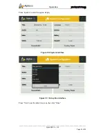
Page 51: ...re 5 18 Press Function Select the highlighted icon Function to access the settings of the function configuration Figure 5 19 Function interface Customers can select Self consumption mode and Grid Charge mode and Controlled Discharge mode Choose Grid Charge and Controlled Discharge to charge and discharge the device according to the time period you need to select ...

Page 52: ...he inverter Step 2 turn off the AC air switch on HV900112 Step 3 turn off the moulded case circuit breaker MCCB on HV900112 Note Check that all of the switches are off The system will be switched on automatically if it is still powered after 5 min Online Monitoring Access Registering You can create a new account on our webserver for the normal monitoring In addition a part of our warranty is based...

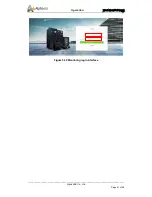
Page 53: ...__________________________________________________________________________________ Alpha ESS Co Ltd Page 51 of 59 Your Smart Energy Operation Figure 5 20 Monitoring login interface ...

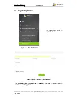
Page 54: ...o Ltd Page 52 of 59 Your Smart Energy Operation Registering License Figure 5 21 Menu for installer Click install new system to register the license Figure 5 22 System registering interface Input S N serial number Check Code License No Date Name and Contact No to complete the registering process ...

Page 55: ...e relocation or decommissioning Temporary warning signs or barriers must be posted during electrical connection and maintenance work to prevent unrelated persons from entering the area where electrical connections or maintenance are carried out Appropriate protective measures should be taken while working on the BESS system for operation repair maintenance relocation or decommissioning see section...

Page 56: ...re Check AC output connections are secure Check communication cable connections are secure Check AC DC switch fan Operating Environment Visual inspection to be completed every six months 1 Carefully observe whether the battery system equipment is ineffective or damaged 2 When the system is running listen to the system for any abnormal noise 3 Check whether the voltage temperature and other paramet...

Page 57: ... are secure and terminal connections haven t got any signs of overheating 5 Monitor the voltage temperature and events on the EMS module and see if the BLMU s collection line connection terminal terminal block communication line connection are secure and not damaged 6 Check whether the EMS module of the system equipment monitoring system and other related equipment are the correct component module...

Page 58: ...ell discharge under temperature fault Disch Low Temp Contact with Alpha service Cell under volt fault Cell Low Volt Contact with Alpha service Insulation resistan fault IR_Fail Contact with Alpha service LMU Communication fault Commu_fail_LMU Check communication connection between batteries LMU and LMU battery and HV900112 LMU and BMU Cell over temperature fault Cell Ov Temp Contact with Alpha ser...

Page 59: ...inverter to come to normal If the fault still exists please contact Alpha service 5 Grid Reverse Check the phase sequence connection of the grid and restart after correction 6 Islanding 1 Check to confirm if the grid is reliable 2 Check the circuit breaker for normal closure If the fault still exists please contact Alpha service 8 GND fault Check the grounding wiring If the fault still exists plea...

Reviews: