ADM-VPX3-9Z2 User Manual
V1.1 - 16th January 2020
Monitor
Purpose
12V0
12V Board Input Supply
5V0
5V Board Input Supply
3V3
Board Input Supply
2V5
FPGA IO Supply
1V8
FPGA IO Supply
0V85
FPGA Core Voltage
MGT_AUX_1V8
FPGA MGT Aux Supply
1V2
DDR4 SDRAM, Target FPGA memory I/O
FMC_VADJ
Variable FMC IO Supply
0V85_BRAM
FPGA Block RAM Voltage
MGT_1V2
FPGA MGT Vtt Supply
MGT_0V9
FPGA MGT Vcc Supply
PSINTFP_0V85
MPSoC PS Core Supply
Temp1
microcontroller internal temperature
Temp2
TMP422 internal temperature
Temp3
FPGA on-die temperature (measured in TMP422)
Table 24 : Voltage and Temperature Monitors (in microcontroller)
The system monitor sensor values can be read via usb using the avr2util utility contained within the Alpha Data
ADM-VPX3-9Z2 SDK.
3.9.1 Automatic Temperature Monitoring
The system monitor checks that the board and FPGA are being operated within the specified limits. If the
temperature is close to the limit, a "Warning Alarm" interrupt is set.
If a limit is exceeded, a "Critical Alarm" interrupt is set. After the Critical Alarm is set, there is a 5 second delay
before the system monitor unconfigures the FPGA by asserting its "PROG" pin.
The purpose of this mechanism is to protect the card from damage due to over-temperature. It is possible that it
will cause the user application and, possibly, the host computer to "hang".
The temperature limits are shown in Table Temperature Limits. Note that the Min and Max values include a 5°C
margin to prevent measurement errors triggering a false alarm.
.
Target FPGA
Board (uC and PCB)
Min
Lower
Warning
Upper
Warning
Max
Min
Lower
Warning
Upper
Warning
Max
Extended
-5°C
+5°C
+95°C
+105°C
-5°C
+5°C
+80°C
+90°C
Industrial
-45°C
-35°C
+95°C
+105°C
-45°C
-35°C
+80°C
+90°C
Table 25 : Temperature Limits
3.9.2 System Monitor Status LEDs
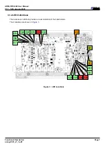
LEDs D13 (Green) and D18 (Red) indicate the microcontroller status.
Page 18
Functional Description
ad-ug-1323_v1_1.pdf


