Installation & Systems Manual RUBIDIUM SERIES
Page 63
3.28
VL
: LTC Distribution and Converter Module
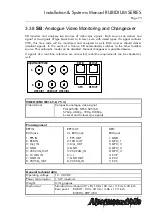
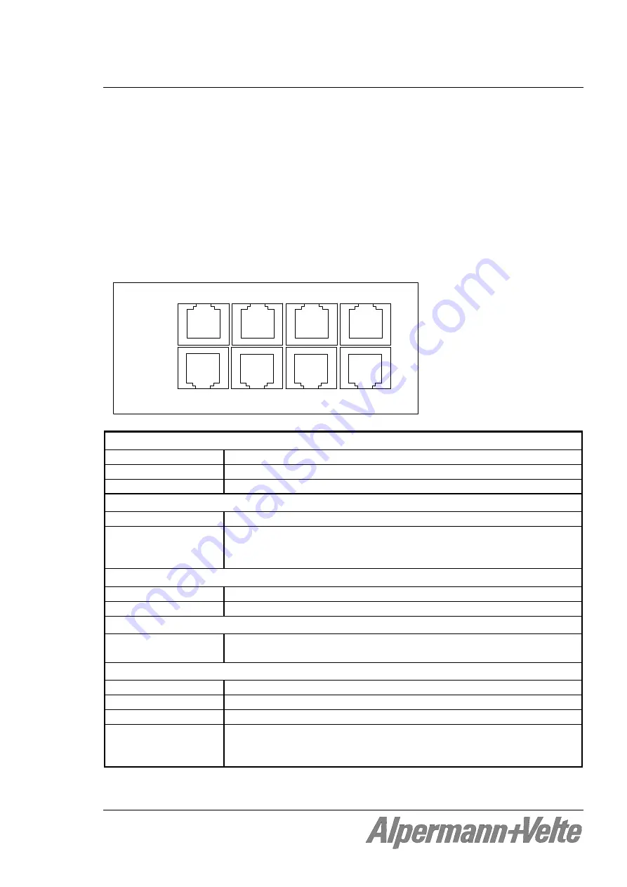
The VL module is a signal distribution and amplifier with two separate LTC readers and four
independent LTC generators, four RS232 and RS4222 outputs and four output stages for
impulse telegrams. All output signals are phase-locked to the LTC reference input.
LTC time and user (binary groups) can be read, processed and converted. The independent
outputs can be set up individually and can generate the processed/converted input data with
various output formats. For example the AlVelte LTC(MTD) can be decoded and
converted to various output formats, so that external devices can display the individual stop
timers or time zone data. Impulse telegram outputs are available to control AlVelte
analogue clocks.
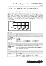
AlVelte
OUT 3
OUT 1
GPI
IN
8 . . . . . 1
8 . . . . . 1
8 . . . . . 1
8 . . . . . 1
OUT 2
VTR IN
LOOP
1 . . . . . 8
1 . . . . . 8
1 . . . . . 8
OUT 4
1 . . . . . 8
LTC input
:
Format
according to ANSI/SMPTE 12M-1-2008, balanced
Signal level
100 mV
p-p
- 5 V
p-p
, auto-ranging
Frequency
Reference LTC:19 - 33 frames/s; VTR LTC: 1.6 - 2500 frames/s
LTC outputs
:
Output impedance
< 50
Ω
Signal level
adjustable:
balanced use: from –17 dBu/0,31 V
p-p
to +13 dBu/9,8 V
p-p
unbalanced use: from –23 dBu/0,16 V
p-p
to +7 dBu/4,9 V
p-p
Serial outputs
:
RS422 according
to
TIA/EIA-422 standard, 2400 to 115200 bps
RS232
according to EIA/TIA-232 standard, 2400 to 115200 bps
Impulse outputs
:
Format
12 V impulse telegram output used to control analogue clocks of the
AlVelte MTD system
Others
:
Operating voltage
15 - 30 VDC
Power consumption
3.0 W maximum (without load at the VCC12_OUT pins)
Weight
0.4 kg approx.
Mechanical
2 circuit boards (W x D): 100 x 160 mm / 3.94 x 6.30 inch
Rear panel: RUB H1: 103 x 44 mm / 4.06 x 1.73 inch
RUB H3: 8HP, 3RU

