background image

ALMECO nv 

Air and water technologies

Royennestraat 51, B-7700 Moeskroen

[email protected] - www.almeco.eu

12

EP10A

 compact blower

!


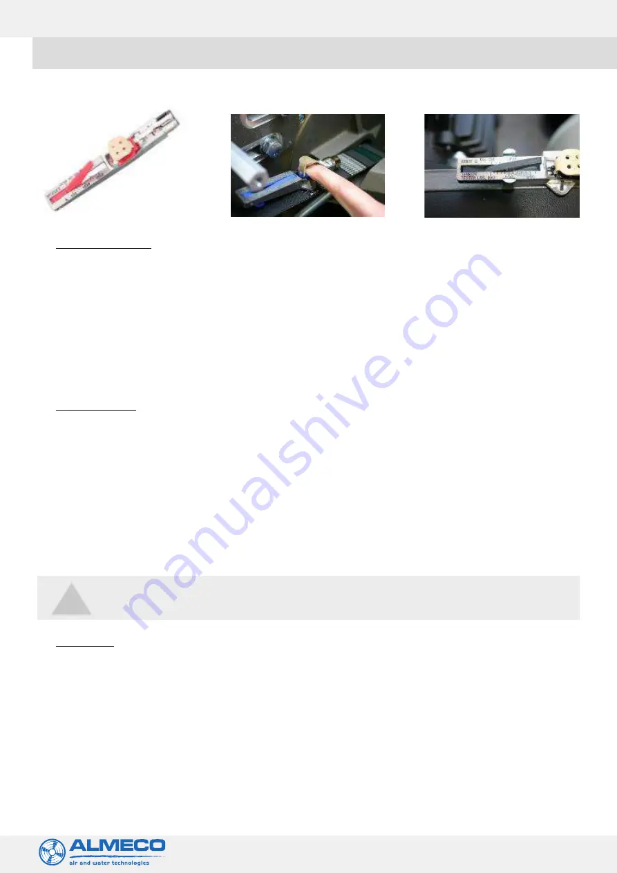
Image: EP10A Tension Gauge (ref: Krikit Gauge)


To remove a drive belt 

• 

Isolate the power supply.

• 

Remove the belt guard.

• 

Disconnect any ducting.

• 

Loosen the 4 off M10 bolts clamping the motor mounting plate to the blower back plate, using a 17mm spanner or  


socket.

• 

Slacken the 2 off M12 nuts on adjustment screw above and below adjustment anchor cast into motor mounting   


plate, slacken top nut using a 19mm spanner, to allow the blower head/back plate assembly to drop sufficiently to  


facilitate the removal of the belt.

• 

After removal ensure the pulleys are clear of any dust or debris. If the belt is to be re-used wipe with a dry cloth before  


attempting to refit.


To refit a drive belt 

• 

Fit the new belt over the pulleys ensuring that it is correctly aligned with the poly-vee pulleys. Do not force the belt or  


roll the belt onto the pulleys. Ensure the blower head is low enough to allow the belt to clear before attempting to fit.

• 

Using the M12 nuts on the adjusting screw, apply sufficient tension to raise the blower head/back plate assembly into  


its approximate position and lightly tighten the M10 bolts to hold the assembly in place.

• 

Tension using the M12 nut on the upper side of the adjustment anchor checking the tension with ‘Krikit’ tension   


gauge supplied. (Refer to figures 4 & 5). When the correct tension is achieved (50kg or110lbs on the scale), lock    


adjuster by tightening the M12 nut on the underside of the adjustment anchor and tighten M10 bolts to approx.   


20N/M.

• 

After fitting a new belt, the tension should be re-checked after the unit has been run between 10-20 minutes. This is  


due to initial stretch of a new belt.

• 

Only drive belts supplied by Almeco should be used.


Blower heads


The EP10A’s head assembly comprises:


a. fan case


b. inlet ring


c. back plate

  d. 

impeller


e. spindle assembly


When replacing this compact blower head, the pulley and hub position must be checked. [Please note - This blower head  


is a newer design with a different pulley position to older units supplied pre 2002.]


For standard metric frame motors the hub that the pulley mounts on must be 20-21mm from the motor flange face. If it is 


a NEMA motor this dimension must be 14-15mm.

Drive belts supplied by Almeco should be used.

Summary of Contents for ACI EP10A

Page 1: ...www almeco eu DRYING SYSTEMS EP10A Compact blower Installation operation maintenance Instruction manual EP10A compact blower...

Page 2: ...information 4 a Description and model identification b Equipment arrival 3 Key features and dimensions 5 a Key EP10A features b Key EP10AH features c Illustration further EP10A key features 4 Install...

Page 3: ...of starts and stops if so then use a timer delay in the control to avoid frequent switching The EP10A blower needs to have airflow passing through it to ensure temperatures are not exceeded The use of...

Page 4: ...or as a hot air version EP10AH where air temperatures of up to 365 F 185 C can be processed Almeco clearly labels each EP10A EP10AH blower unit on the back of the blower head as well as the motor cow...

Page 5: ...er should be cleaned regularly and the main element replaced every six months Drive belt guard Poly V belt Motor pulley Motor IE3 Blowerhead EP10 A Filter Ref B3 003 039 B3 000 185 Pre lter B3 000 147...

Page 6: ...www almeco eu Ref B3 003 037 Thermal cut Hot air Ref ACEP 250H 7 EP10A compact blower c Illustration furtherEP10AKeyFeatures d EP10AHeadOptions Electric Motor Standard Metric or NEMA Filter Assembly B...

Page 7: ...mounting plate is provided to suit the large C face configuration NOTE Allow room for bracket movement during belt replacement Very low vibration levels of these units allow them to be bolted to any...

Page 8: ...r If an inverter is not used use a suitable starter with overload protection star delta starter f Shaft rotation All units rotate counter clockwise when viewing the blower from the cooling fan of the...

Page 9: ...tend the life of the mechanical components and ensure continued efficiency and longevity Removing filter element Step 1 Remove pre filter element by releasing the security nut and washer Use a 17mm AF...

Page 10: ...f the unit is still not dry Re fitting filter elements Once the main filter element and the pre filter sock are thoroughly dried they can be re fitted to each other Refit the filter and its cover and...

Page 11: ...2 nuts on the adjusting screw apply sufficient tension to raise the blower head back plate assembly into its approximate position and lightly tighten the M10 bolts to hold the assembly in place Tensio...

Page 12: ...ith the poly vee pulleys Do not force the belt or roll the belt onto the pulleys Ensure the blower head is low enough to allow the belt to clear before attempting to fit Using the M12 nuts on the adju...

Page 13: ...lter Maintenance Damaged hose lining Replace damaged hose Air leaks in system Check replace damaged hose and clips Drive belt slipping Worn Pulley Replace transmission parts Incorrect speed from contr...

Page 14: ...cal overloading Exceeding rated CFM Reduce open area of air delivery devices i e slot width of Airknives Blower not piped to system Only run blower when connected to the operating system Never run in...

Page 15: ...espective manufacturer s policy Motors and other items for which a national service network is in place should be sent directly to that manufacturer s representative for the most prompt service Almeco...

Reviews: