background image

Page 21

ALLPRO Imaging

Erase Only Mode

The ScanX can be used to just erase PSPs .  This is done simply by selecting the Erase option (instead of 
Scan) from the installed authorized imaging software when activating the ScanX . During the Erase Only 
mode just the in-line eraser is activated .  The PSP is transported through the ScanX as a normal scan 
but is not scanned . No image is acquired and the PSP is erased and ready for reuse as necessary .  See 
Erasing PSPs on page 18 .

IMPORTANT:


Never power down the system during a scanning session.

IMPORTANT:

  PSPs will 

not

 be erased after scanning when operating the ScanX with the eraser disabled. 

PSPs must always be erased prior to exposure to X-rays for new images.

Scanning Plates without Erasing 

The ScanX can be operated with the in-line eraser feature turned off . When the eraser mode is disabled, the 

ScanX scans the same as when the eraser is enabled except that the PSPs are 

not

 erased after scanning . 

Scan an PSP without erasing the image by performing the following procedures .

1 . Activate the scanner by performing the procedures on page 19 .

Note:

  Always check that the eraser mode is disabled upon activation.


The ScanX defaults to the mode last used at power turn off.  

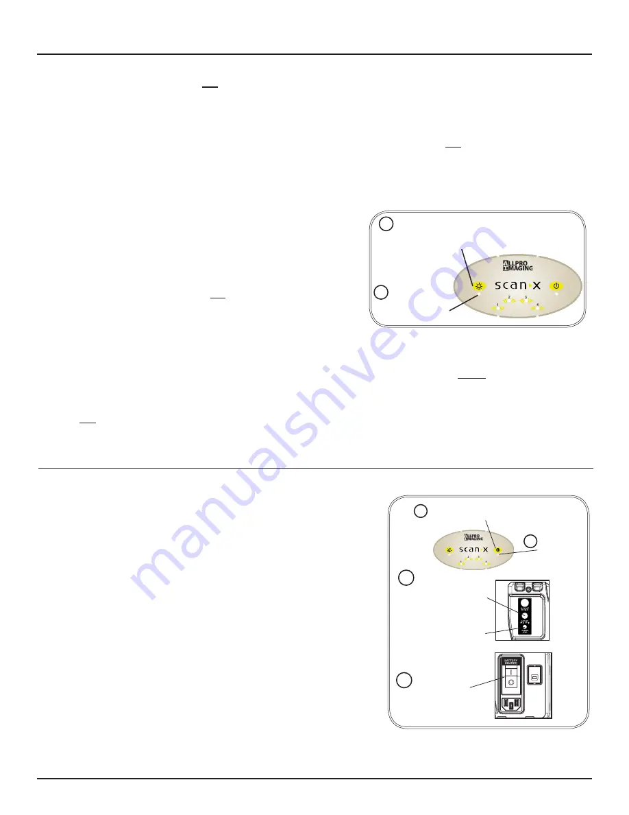
Figure 11 . Eraser Disable

2 . If necessary, disable the eraser mode of operation by 

pressing the ERASER switch located on the Membrane 

Keypad .  

3 . Verify that the blue LED indicator located below the 

ERASER switch is extinguished to indicate that the Erase 

function is OFF . The PSP will 

not


be erased after scanning .

4 . Insert the PSP to be scanned into the ScanX by performing 

the Scanning and Erasing Plates procedures provided 

on the previous page .

Press the ERASER 

switch to disable the 

erase mode. 

2

Verify that the 

ERASER indicator 

is extinguished  

3

IMAGING PROCEDURES

POWERING DOWN THE SYSTEM 

ScanX Power Removal

The battery power on ScanX models operating from the built in 

battery should be turned off when not used for extended periods . 

ScanX models operating from AC Mains are designed to be left 

on continuously during the active day .  At the end of the day, or 

whenever desired, power down the system as shown by Figure 12 

and the following steps: 

1 . Place the ScanX in the Standby mode by pressing and holding 

the membrane READY switch on the Membrane Keypad 

(approximately 2 seconds) until the green LED above the 

READY switch extinguishes .

2 . Verify that the READY indicator extinguishes .
3 . Remove the power to the ScanX by performing one of the 

following steps depending on operating power used .

a . When operating from the battery, press the BATTERY push 

button to place the switch in the OFF (raised) position . 

Verify the CHARGE LEVEL indicator extinguishes . 

b . When operating from AC Mains, place the Main Power 

switch to the OFF (0) position . 

Verify that the 

READY indicator 

extinguishes

Press & Hold (2 secs) 

READY switch to set 

ScanX in Standby. 

1

When Operating from Battery 

Set BATTERY ON/OFF Switch to 

OFF Position

Check CHARGE LEVEL 

Indicator extinguishes

or

2

3a

3b

When Operating from AC Mains 

Place Main Power Switch (I/0) 

to OFF (O) position.

Figure 12 . System Power Down

Summary of Contents for ScanX trek D5000-T

Page 1: ...Operator s Manual Di g i tal Ima ging Sy s te m Part Numbers D5000 T and D5000 TB ScanX Trek without Battery D5000 T ScanX Trek with Battery D5000 TB...

Page 2: ......

Page 3: ...y listed below including devices with or without battery power Device Name Part No No Battery With Battery Trek D5000 T D5000 TB Designed and built exclusively for the demanding conditions encountered...

Page 4: ...y lead to a reduced level of safety of the resulting system Use of ACCESSORIES or cables other than those specified or provided by the manufacturer may result in increased EMISSIONS or decreased IMMUN...

Page 5: ...in hazardous radiation exposure The laser is on only during an active scan Only a trained technician from an authorized dealer should remove a cover from the ScanX Direct eye contact with the output...

Page 6: ...RE TO BEAM CLASS IIIb LASER PRODUCT COVER REMOVED MAKES THIS DEVICE A The ScanX is a Class I Laser Product Class 1 Laser Product IEC This warning label identifies the ScanX as such a product and descr...

Page 7: ...h regard to safety reliability and proper functioning only if assembly resetting changes or modifications and repairs have been carried out by an authorized dealer and if the equipment is used in conf...

Page 8: ...e received If any item is missing notify your dealer UNPACKING AND INSPECTION Figure 1 Typical ScanX Trek Product Family Packaging ScanX Unit Accessory Kit Accessory Kit Contents Accessory Literature...

Page 9: ...or for complete mobility inserted into either an optional hard or soft carrying case for easy and safe transport anywhere image scanning is required Rechargeable Battery The ScanX Trek has a model wi...

Page 10: ...midity 5 95 Non condensing Note Resolution of the ScanX is dependent on operating mode and specific imaging plate type used Resolution LP mm Horizontal Vertical 3 8 to 5 0 3 8 to 7 Compliance Data Las...

Page 11: ...x64 processor Microsoft Windows 7 Professional Enterprise or Ultimate with Service Pack 1 for an Intel 32 bit or an Intel 64 bit extended x64 processor Microsoft Windows 8 1 Professional or Enterprise...

Page 12: ...computer cm centimeter GB gigabyte 230 109 bytes GHz Gigahertz 109 of Hertz H height Hz Hertz cycles per second IEC International Electro technical Commission IMS Image Management Software IP imaging...

Page 13: ...t in the ON position depressed and flush with the panel this switch allows the ScanX to operate from battery power While engaged the CHARGE LEVEL Indicator illuminates 2 When placed in the OFF positio...

Page 14: ...ote When the Eraser Status Indicator displays a burst of approximately 5 quick flashes it is alerting the user that the erase function is reduced due to a high temperature condition in the red LED era...

Page 15: ...11 necessary to support ScanX operation Set up the computer according to the manufacturer s recommendations 2 Verify that an authorized Imaging Software and the supplied USB drivers are installed prop...

Page 16: ...e internal battery must always be charged prior to using To reach the full operational power level charge for at least 3 hours before using for the first time and on subsequent uses Refer to figure 6...

Page 17: ...with the plates CAUTION Use a Plate Protector for each plate PSPs may be exposed in cassettes and scanned without Plate Protectors however greater care must be exercised to not expose the PSP to light...

Page 18: ...ll be acquired Method 2 Perform the Activate Scanner and the Scanning and Erasing Plates procedures on pages 19 and 20 This method scans the plate and the imaging software may acquire a junk image sca...

Page 19: ...the ScanX The PSP is now ready to be scanned Activate Scanner Refer to Figure 9 and activate the ScanX via AC power or the internal Battery power by performing the fol lowing procedures 1 Refer to Fi...

Page 20: ...by both guide flaps resting on the inlet ring which further aids in alignment 5 At this point all four track lights will turn yellow indicating the PSP has been sensed and the Scanner is transporting...

Page 21: ...indicate that the Erase function is OFF The PSP will not be erased after scanning 4 Insert the PSP to be scanned into the ScanX by performing the Scanning and Erasing Plates procedures provided on the...

Page 22: ...not run Verify Computer System requirements Page 11 Make sure that the READY switch is set to ON and the green indicator is lit Reconnect the cable Check for tightness Replace if necessary Verify tha...

Page 23: ...long in cassette Partial image erasure due to exposure to light during han dling of the PSP Make sure the ScanX is operating with both eraser strips turned on blue LED indicator below the ERASER switc...

Page 24: ...no effect on the quality of the image and should be expected under normal conditions If the phosphor side is scratched make sure the plates are being handled properly and not being dragged from the Sc...

Page 25: ...pense the malfunctioning system back to ALLPRO Imaging in the same shipping container All equipment under warranty require a Return Materials Authorization RMA issued by Technical Services Items retur...

Page 26: ...ALLPRO Imaging Page 26 NOTES...

Page 27: ...Page 27 ALLPRO Imaging NOTES...

Page 28: ...and software to facilitate smooth and efficient radiography procedures Thousands of ALLPRO Imaging products have been sold globally installed and serviced through our network of authorized dealers Pr...

Reviews: