MS888G2 User Manual
10
Alloy Computer Products Pty Ltd Copyright ©2006
•
Installing Optional 8 Port Copper or Fibre Modules
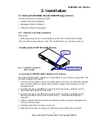
• Connecting the Module to the Chassis:
All modules are hot-swappable, so you can plug or unplug them while the power is applied to the
switch.
1. Verify that the type of module you have selected for use will be compatible with the type of
fibre optic cable that is to be used.
2. Verify that the type of module you have selected for use will be compatible with the fibre optic
transceiver at the other end of the link (e.g. – compatible wavelength and standard).
3. Slide the module along the slot and ensure that the module is properly seated against the
socket/connector.
4. Install the media cable for network connection.
5. Repeat the above steps, as needed, for each module to be installed into the switch.
•
Copper Ports - Cable Installation
Please Note:
⇒
The RJ-45 ports on the MS888G2 support MDI/MDI-X auto-crossover
functionality. This enables use of either straight-through or crossover UTP cable
types; the RJ-45 ports will automatically be configured to suit the characteristics of the device
at the remote end of the link.
⇒
The RJ-45 ports on the MS888G2 support Nway auto-negotiation; the ports will automatically
be configured to be compatible with the speed and duplex settings of the device at the remote
end of the link.
⇒
The minimum grade of cable for use with the switch is Cat. 5 grade UTP or STP. Higher
grades of UTP/STP cable may also be used to connect to the copper RJ-45 ports.
1. Depress the clip on the RJ-45 connector and push into the RJ-45 port. Release
connector and ensure that the cable connector is securely locked into the RJ-45 port.
2. Repeat the above steps, as needed, for each RJ-45 port to be connected.
Fig.
2-2: Installation of optional Copper or Fibre Module
SFP port
Mini-GBIC module
Empty Module Slot
8 Port Fibre or
Copper Module


