23
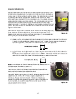
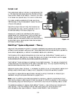
Figure 24:
The indicator tip
is aligned directly under the
micro-hub pivot pin
Procedure:
1)
If proceeding from the previous section, remove the adapter
plate and indicator and separate the two components so the
indicator can be used by itself.
2)
Manually position the indicator tip to about a 25º forward
angle, and secure the indicator to the platen using double
sided adhesive tape so the indicator tip is facing the micro-
hub assembly. Rotate the indicator bezel so the “0” is rear-
facing (Figure 24).
3)
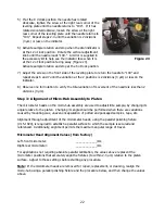
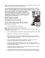
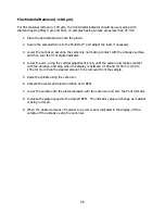
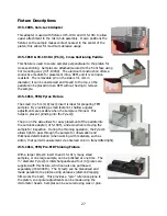
Attach a parallel polishing fixture (#15-1020) to the
MultiPrep™ head and lower the spindle using the spindle
riser.
4)
Activate sample rotation and stop when the pivot pin is over
the contact point of the indicator tip (Figure 24).
5)
Lower the arm using the vertical adjustment knob until the
bottom of the fixture makes contact with the indicator tip
and the needle of the dial indicator is aligned with the “0.”
6)
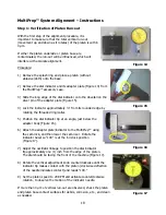
Activate full sample rotation and stop it when the indicator
tip is directly beneath the first micrometer head (Figure 25).
7)
Adjust the micrometer head to return the dial indicator
needle back to “0,” in the opposite rotational direction of its
movement during Step 6. For example, if the indicator
moved clockwise from “0,” return it counterclockwise by
rotating the micrometer head counterclockwise.
8)
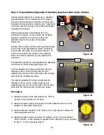
Activate full rotation and stop it when the indicator tip is
directly beneath the second micrometer head (Figure 26).
9)
Adjust the micrometer head to return the indicator needle to
“0.”
10)
Activate full rotation until the fixed pivot pin is located over
the tip of the dial indicator (Figure 24).
11)
Adjust the vertical adjustment knob until the indicator needle
is at “0.”
12)
Repeat steps 6-11 until less than 4 µm of variation are noted
on the dial indicator over a full 360º rotation.
13)
Note the left and right micrometer settings to assist with future calibration.
Figure 25
: The indicator tip
is aligned directly under the
first micrometer head
Figure 26
: The indicator tip is
aligned directly under second
micrometer head
Summary of Contents for MultiPrep System 15-2000-GI
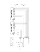
Page 35: ...35 MultiPrep System Wiring Diagrams ...
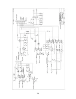
Page 36: ...36 ...
Page 37: ...37 ...
Page 38: ...38 ...
Page 39: ...39 CE Certificates ...
Page 40: ...40 ...
Page 41: ...41 ...
Page 42: ...42 This page has been left blank intentionally ...
Page 43: ...43 This page has been left blank intentionally ...


