Allied HO-PAC 400B Safety, Operation, Maintenance And Parts Download Page 18

Allied Construction Products, LLC www.alliedcp.com 

TM577696_HP400B_16aug


6.0 Mounting Information – [cont'd] 


6.1.3 XSF Mounting Kits 


IMPORTANT 

Complete information about the carrier is required, 

including the make, model, series and serial 

number. Carriers equipped with a quick coupler 

will require additional information. (NOTE: The 

XSF frame has limited fit-up with carriers equipped 

with quick mounting couplers).  


Match he carrier’s pin diameter with the proper 

mounting kit listed in Table 6.2. Eliminate any gap 

using the supplied spacers having varying 

thicknesses. 


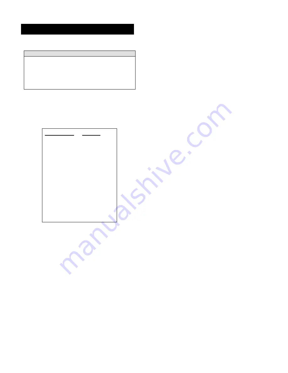
Table 6.2 XSF Mounting Kits


Bucket Pin 


Part No. 

25 mm 

A101735 

30 mm 

100207 

35 mm 

100283 

38 mm 

100364 

40 mm 

100204 

45 mm 

100324 

50 mm 

101808 

1.00” 

100208 

1.25” 

100209 

1.50” 

A100210 


Summary of Contents for HO-PAC 400B

Page 1: ...and training Keep this manual in a convenient location so that it is easily accessible for future reference Contact your Allied Dealer or the Allied Customer Service Department for replacement manuals Inquiries regarding the content of this manual must include effective date shown on inside cover TM577696 Ho Pac Vibratory Plate Compactor Driver Model 400B Safety Operation Maintenance and Parts ...

Page 2: ...may not reflect the product in the future Specifications are based on published information at the time of publication When changes become necessary these will be noted in the table below Earlier dated publications are immediately cancelled and superseded by publications with the most current date recorded Material not in conflict with the most recent effective date shall remain in effect For prod...

Page 3: ...ME ALERT YOUR SAFETY IS INVOLVED Fig S1 Safety Alert Symbol The Safety Alert Symbol Fig S1 either used alone or in conjunction with a signal word is used to draw attention to the presence of potential safety hazards Signal Words DANGER WARNING and CAUTION are signal words used to express severity of consequences should a hazard be encountered DANGER Indicates an imminent hazard which if not avoide...

Page 4: ...es Install protective guards on cab to shield operator against fragments debris Personnel maintain a safe distance from the work tool work zone Identifies lift point Personal Protection Equipment Hearing protection Safety eyewear Gloves Safety shoes Falling object Unsupported loads Crush point Falling part Falls into open excavations Trench collapse Electric Shock Gas Oil under pressure Hot surfac...

Page 5: ...ain a safe distance from the Allied work tool during operation L3 Hot Surface Identifies surfaces of the Allied work tool that become hot during operation L4 Lift Point Decal identifies approved lift points of the Allied work tool L5 Pressure Line Tag A red colored cable tie marked PRESSURE IN is attached to the SUPPLY hose of the Allied work tool for ease of identification between hoses L6 Compan...

Page 6: ... 8 L1 Safety Label Read Instructions Manual 676984 2 L2 Safety Label Stay Clear 676981 2 L3 Safety Label Hot Surface 676983 1 L4 Safety Label Lift Point 676982 4 L5 Info Tag Pressure I D 818676 1 Located on Supply Line L6 ID Label Allied Logo 676653 2 L7 ID Label HO PAC 577554 2 L8 ID Label Model 400B 577691 2 Items L8 L10 Not included in set L9 ID Label Made In USA 815696 1 L10 ID Tag Equipment I...

Page 7: ...nders The standard safety precautions expected and required of those working in construction shall include but not limited to Locating existing underground service and utility lines Erecting barriers to control entry to established work zone The use of appropriate personnel protection equipment Federal State Local and OSHA Construction Guidelines and Regulations Use the Allied equipment in accorda...

Page 8: ...o prevent an unsafe situation by means of a guard safety messages appear on the equipment warning personnel of a recognized hazard Additional guarding not included with the Allied equipment is necessary at the operator s station to protect the operator and other nearby personnel against flying debris from material being cut or demolished Do not handle demolish or cut material overhead without prop...

Page 9: ...Where to Find the Serial Number 2 2 2 Equipment Identification Tag 2 2 3 Owner s Record of the Equipment 2 3 0 Warranty Protection Summary 3 3 1 Overview 3 3 2 Owner s Responsibilities 3 SECTION Page 3 3 Allied Product Policies 4 4 0 Product Information 5 4 1 Description and Application 5 4 2 Familiarization of Major Subassemblies 5 4 3 Principle of Operation 5 5 0 Ho Pac Selection and Application...

Page 10: ...ead Instructions iv Stay Clear iv Hot Surface iv Lift Point iv Pressure Line iv Model Identification iv Equipment Identification Tag iv S 3 Placement of Labels on Equipment v 2 1 Location of Equipment Serial Number 2 2 2 Equipment Identification Tag 2 4 1 Major Subassemblies 5 5 1 Allied Conversion Kit with AC Series Valve 6 6 1 Flat Top Frame and Mounting Bracket 7 6 2 XSF Top Frame 7 7 1 Supply ...

Page 11: ...he information necessary for the safe and proper use of the Allied equipment This manual includes a spare parts list Figures shown in the Parts Information Section of this Manual are for the purpose of parts identification and not intended for use in the repair or service of the equipment This document is published solely for information purposes and should not be considered all inclusive If furth...

Page 12: ...the information provided in Section 1 of this manual 2 3 Owner s Record of the Equipment Your local Allied dealer requires the Product Name Model and Serial Number to better assist you with questions regarding parts warranty operation maintenance or repair This information should be copied from the Equipment Identification Tag to the space provided below Indicate the date in which the Allied equip...

Page 13: ...ng of the Allied equipment adhere to the following Read and thoroughly understand the information and procedures detailed in this manual Understand proper operating techniques for all recommended applications Use the Allied attachment only if it is in sound operating condition Take prompt action to rectify any faults that if left uncorrected could lead to personal injury or further damage Use the ...

Page 14: ... methods Inattention to re lubrication and other maintenance requirements Misuse Unapproved applications Inadequate or absence of training Use of non genuine Allied replacement parts Unapproved modifications Use of grease which is not or is only conditionally pumpable The use of a lubricant type that is unsuitable for the application Contaminated lubricants Improper disposal of used or contaminate...

Page 15: ...ation is affected by the motor s speed of rotation weight of the eccentric mass and the distance between eccentric mass and shaft The vibratory action and impulse force is transferred through the attached compaction plate Control Valve All Ho Pac models come standard with the multi function control valve Benefits include optimized operation with improved reliability of critical components such as ...

Page 16: ... underperforming compactors are less economical to use because compaction is limited to smaller lifts and require additional passes This generates other inefficiencies as longer running cycles result in loss of time increased energy consumption and component wear Optimum efficiency is achieved only when proper operating technique is employed How many passes it will take along with the duration wil...

Page 17: ... carrier It is attached to the carrier in the same manner as mounting a bucket Allied offers an array of mounting brackets sold separately to fit virtually any carrier including those equipped with pin grab or hook type quick mounting couplers Each flat top frame has a series of holes located in the top plate Dimensions of the bolt pattern are located in Section 12 of this manual Hydraulic breaker...

Page 18: ...quick coupler will require additional information NOTE The XSF frame has limited fit up with carriers equipped with quick mounting couplers Match he carrier s pin diameter with the proper mounting kit listed in Table 6 2 Eliminate any gap using the supplied spacers having varying thicknesses Table 6 2 XSF Mounting Kits Bucket Pin Part No 25 mm A101735 30 mm 100207 35 mm 100283 38 mm 100364 40 mm 1...

Page 19: ...acturer For carriers equipped with a quick coupler refer to the owner s manual furnished by the coupler manufacturer for instructions The machine operator and an assistant shall perform the following procedure 1 Operator Move carrier and Ho Pac to a firm level surface Position the Ho Pac with the hose side facing toward the carrier 2 Assistant Check that the Ho Pac is stable and all loads are supp...

Page 20: ...e part number of the valve can be found stamped into the body above connection port T2 1 Raise the Ho Pac off the ground and operate the bucket cylinder to ensure hoses will not be pinched or restricted Fig 7 2 Check hose length routing for unrestricted movement 2 Briefly test Ho Pac for proper operation Stop and check for hydraulic leaks Tighten hoses and connections as necessary IMPORTANT Read u...

Page 21: ...t be qualified in handling procedures The operator must have an unobstructed view of the assistant and load at all times The operator shall maintain full control of the machine at all times Crush hazard Keep clear of crush points and moving parts All directions and signals must be agreed upon in advance Take signals from only ONE person IMPORTANT Collect fluids in a suitable container Clean up spi...

Page 22: ...Ho Pac with workers in close proximity of work zone Clear all personnel from work area before the Ho Pac is operated CAUTION Injury from flying debris Personal protection equipment including safety eyewear must be worn when operating or servicing this equipment Risk of hearing impairment or loss Hearing protection must be worn by all personnel exposed to prolonged high noise levels WARNING Injury ...

Page 23: ...ost responsive to compaction through vibratory action Moisture content is also critical to achieving maximum compacted densities of fill material Fill materials may need conditioning prior to compaction IMPORTANT Always practice proper operating techniques Do not allow mounting frame to contact base plate Spring mount and frame damage may result Stretch the spring mounts no more than approximately...

Page 24: ...harsh applications or extreme conditions For example if using water content hydraulic fluid or when operating under conditions of extreme temperatures dust high elevations or extended continuous use components will require more frequent monitoring Use regular component inspection to determine if interval adjustment is warranted While the frequency of inspections and maintenance depend primarily on...

Page 25: ...wing conditions are present Leak at end fitting that cannot be eliminated through proper tightening techniques Outer coverings are chafed or cut Wires are exposed Outer coverings are ballooning Flexible part of the hoses are kinked Outer covers have embedded armoring End fittings are displaced 9 4 Oil Level and Quality of Carrier CAUTION Follow the recommended service intervals from the carrier ma...

Page 26: ...IMPORTANT Obey all local regulations for the proper disposal of all used fluids 9 7 5 Bearing Installation IMPORTANT Handle new bearings with care to prevent damage Do not remove from packaging until ready to install CAUTION Bearings are interference press fit Apply contact pressure to the outer race only Do not hammer on the bearing rings 1 Clean the bearing housing 2 Lightly lubricate bearing s ...

Page 27: ...of a bolt in a blind hole With a nut and bolt combination a hardened washer must be used under the element to be turned AND the element not turned must be prevented from rotating during tightening All threads must be free of damage and foreign debris Surfaces to be bolted must be flat Do not apply thread lock compound to the bolt threads unless instructed to do so Lubricate bolt threads IMPORTANT ...

Page 28: ...6 65 88 1 2 85 115 IN1 2 XR 140 190 9 2 1 Tightening Method Bolts should be systematically tightened starting from the most rigid part of the joint A hardened washer must be used under the head of a bolt in a blind hole When a bolt and nut are used a hardened washer must be used under the element to be turned The part not turned must be prevented from rotating during this operation NOTE After bolt...

Page 29: ...4 Secure hoses to unit to avoid accidental damage 5 Lift attachment at recommended lift points Refer to the Safety Section of this manual for their location 6 Stabilize and secure the attachment adequately for transport 10 1 2 When the attachment is transported while installed on the carrier 1 Remove all loose debris from attachment 2 If the swivel assembly is installed lock swivel position with b...

Page 30: ...oo low Check hydraulic supply system Correct as required Failed bearing Inspect and replace bearings Motor worn or motor seals failed Inspect and replace motor Operation smooth but at reduced speed Flow too low Check carrier output If motor or flow regulator valve was replaced check that the motor and valve are properly matched This Allied work tool is not self powered Its performance level is aff...

Page 31: ...PSI Steadily increase load with restrictor valve on the flow meter Oil Temperature Oil temperature must be at normal operating temperature while testing Stop test if temperature exceeds 176 F 80 C Relief Pressure Crack Slowly close restrictor valve until pressure gage indicates relief valve has cracked open Relief Pressure Static After cracking pressure is reached further adjust restrictor valve u...

Page 32: ...nd Adjust the engine s rpm to the normal operating speed and set operating mode to work tool The test can begin after the normal operating temperature is reached Start the work tool and record the pressure reading It s normal for the pressure reading to increase and decrease as the carrier applies varying amounts of down pressure against the springs Compare your results with the values listed in t...

Page 33: ...cracks open Static Relief Pressure Also referred to as Full Relief Pressure The pressure measured at the moment the relief valve has opened fully and all oil is by passed Opening Curve The dynamic pressure is always less than the static pressure A relief valve adjusted to a dynamic pressure of 3000 psi 200 Bar will crack open when the preset point is reached but fully opens at a higher pressure Th...

Page 34: ...or from over speeding 2 Pressure control Protects the hydraulic components from over pressure This is factory pre set at the maximum operating pressure plus 200 psi 14 bar 3 Anti cavitation circuit Controls deceleration of the hydraulic motor and eccentric mass Also protects motor from damage on circuits not set up with an open return 4 Return line check valve Prevents reverse flow to the hydrauli...

Page 35: ...n Area Ft 2 m 2 Std 2 3 0 21 Hose Size ᴓ Inch mm Pressure 5 8 16 Return 5 8 16 Weight e Lbs kg Std 375 170 Carrier Range f Lbs 1 000 kg 1 000 3 12 1 6 5 4 Sound Power Level DBA LWA 106 Est d a Proper pairing of motor and valve with the carrier s oil flow is critical to reach target soil density and machine efficiency Optimal motor speed RPM is attained only when the carrier s hydraulic circuit pro...

Page 36: ...M577696_HP400B_16aug 26 12 0 Technical Information cont d 12 9 General Dimensions The Ho Pac is offered in multiple configurations Pay strict attention to values figures captions and notations Fig 12 5 Shown is Standard 400B with Flat Top Frame IN1 2 XR ...

Page 37: ...rther identification by serial number The Ho Pac is offered with optional size motors For help with identification of the motor and valve refer to Table 13 3 13 1 2 How to Use this Manual The Allied work tool consists of separate components and partial assemblies Components are identified with the aid of figures captions item key part name and quantity If needed remarks and specifications will fur...

Page 38: ...HO PAC 577685C w IN1 2 XR Flat Top Mounting Frame 1 Dynamic Assembly Std 577684 1 Refer to Fig 13 2 2 Top Mounting Frame Std 577797 1 Flat Top IN1 2 XR Mtg Family 3 Washer 813292 2 FL3 8 4 Hex Head Bolt 578101 2 3 8 5 Elbow 102698 1 EL90 10MJx10MORB 6 Adapter 677119 4 7 Hose T1 573645 1 22 8 Hose P2 573646 1 21 9 QD Socket 102571 2 10 QD Plug 101570 1 11 Hose 574643 2 12 Valve Varies 1 See Table 1...

Page 39: ...mic Assembly Item Description Part No Qty Remarks Specifications 1 Dynamic Assembly 577684 1 Fig 13 2 Config w 13 x 25 CP Std 16 Lower Assembly w CP 577686 1 Std compaction plate 13 x 25 17 Eccentric Assembly 577683 1 18 Roller Bearing 573260 2 19 Bearing Housing 573312 1 20 Hex Head Bolt 902538 6 3 8 21 Lock Washer 798190 6 3 8 22 Socket Head Bolt 572719 2 7 16 23 Washer 708514 2 7 16 24 Hex Head...

Page 40: ... are no user serviceable parts in the flow regulator valve Contact Allied Technical Service for further information 13 2 Motor and Valve Identification IMPORTANT Incorrect combination of motor and valve will result in poor performance or damage 13 2 1 Motor Identification Refer to Figure 13 3 When the part number of the motor is unknown measure the body length Measure the distance L from the back ...

Page 41: ...Pac Model 400B Serial No Complete information is required Line Description Part Number Quantity Price 1 2 3 4 5 6 7 8 9 10 Your contact information Your Name Company Name Phone Account Number Fax Purchase order Email Shipping carrier See note below Billing Address Shipping Address Note All backordered parts will be shipped when available via the same method as the original order unless initialed a...

Page 42: ...Allied Construction Products LLC www alliedcp com TM577696_HP400B_16aug 32 Notes ...

Page 43: ...Allied Construction Products LLC www alliedcp com TM577696_HP400B_16aug 33 ...

Page 44: ...TM577696_HP400B_16aug ...

Reviews: