background image

508034-02

Issue 2135

Page 8 of 49

Red LED Flash Code

2

Diagnostic Codes / Status of Furnace

Off

No power to control or board fault detected

On

Board fault detected

Heartbeat

1

Control powered - displayed during all modes of operation if no errors are detected

1 flash

Reverse line voltage polarity

2 flashes

Improper earth ground

3 flashes

Burner failed to light, or lost flame during heating demand

4 flashes

Low flame signal - check flame sensor

5 flashes

Watchguard - burner failed to light, exceeded maximum number or retries or recycles

6 flashes

Not used

7 flashes

Primary or secondary limit open or Watchguard mode - limit switch open longer than 3 minutes

8 flashes

Rollout switch open

9 flashes

Pressure switch failed to close of opened during heat demand

10 flashes

Watchguard - pressure switch opened 5 times during one heat demand

11 flashes

Pressure switch stuck closed prior to activation or combustion air inducer

12 flashes

Flame sensed without gas valve energized

13 flashes

Low line voltage

1

 A “Heartbeat” is indicated by a “Slow Flash” - 1 sec on 1 sec off, repeating

2

 Error codes are indicated by a “rapid flash” - the LED flashes X times at ½ second on ½ second off, remains off for 3 seconds then 

repeats.

Last 10 error codes are stored in memory including when power is shut off to the unit. - To recall, press and release button, most 

recent will be displayed first, LED off for 3 sec, then next error code is displayed, etc. To clear error codes, depress and hold button 

longer than 5 seconds.

Table 4. Diagnostic Codes
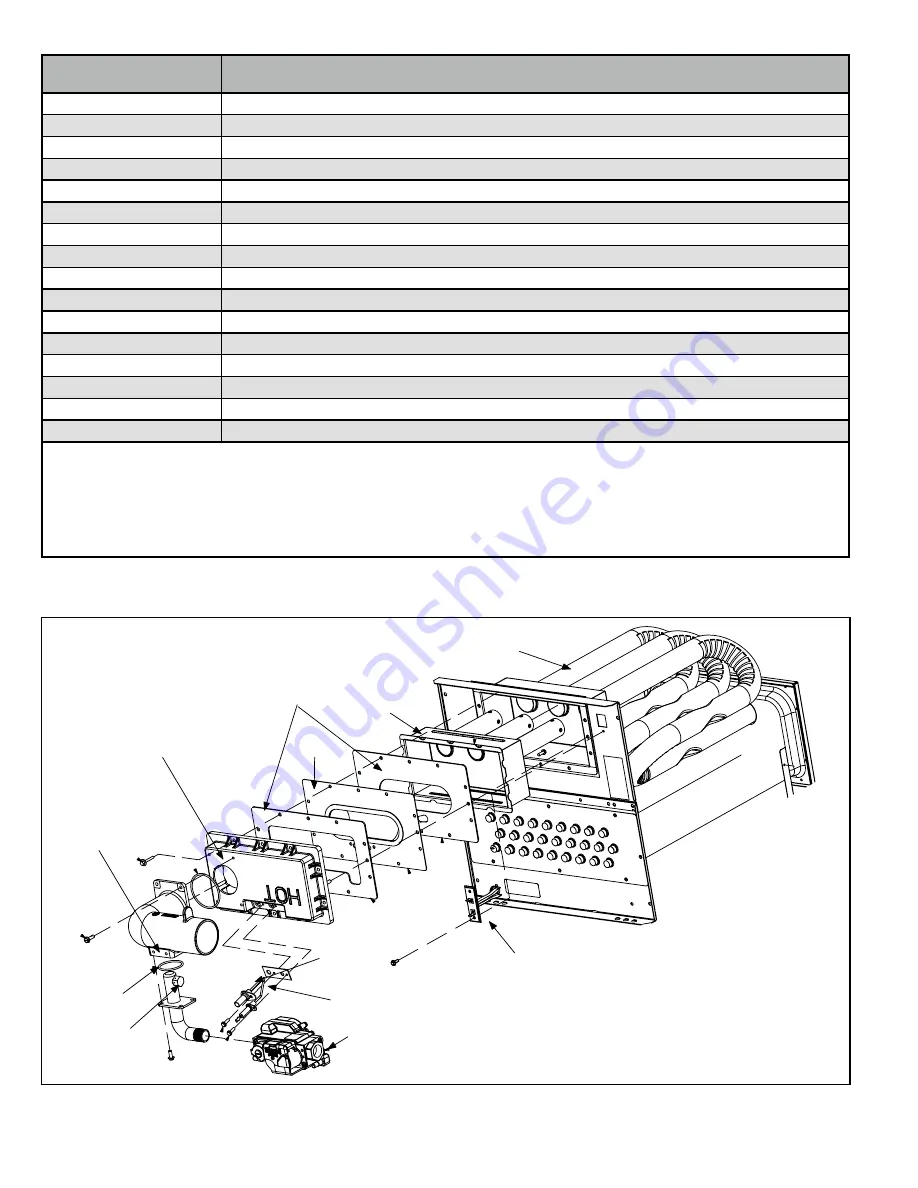
Gas Valve

Primary Limit

Ignitor

Sensor

Gas Orifice

Air Orifice

Rollout Switch

(location)

Air Gas Plenum

Gaskets

Burner

Heat Exchanger

Burner Box

Figure 4. Heating Components

Summary of Contents for 95G1UHEX Series

Page 1: ...supplier WARNING 95G1UHEX series units are high efficiency gas furnaces available in heating input capacities of 40 000 to 100 000 Btuh and cooling applications from 2 through 5 tons Refer to Engineering Handbook for proper sizing Units are factory equipped for use with natural gas All 95G1UHEX units are equipped with a hot surface ignition system The gas valve is redundant to assure safety shut o...

Page 2: ...0 60 1 15 10 9 40 157 NOTE For vent length and clearances to combustibles please reference installation instructions Technical Specifications Accessory List Catalog Number Description External Filter Rack Kits 1 841018 1 pack 16 x 25 1 841039 10 pack 16 x 25 Return Air Base 68W62 17 5 B Width 68W63 21 0 C Width Horizontal Suspension Kit 51W10 80 90 Kit Flush Mount Termination 90 Furnaces only US O...

Page 3: ...m Watts 0 00 1477 338 1289 240 1189 188 940 99 905 88 0 10 1431 353 1262 254 1160 200 918 109 873 97 0 20 1401 360 1244 263 1135 209 894 121 839 108 0 30 1372 374 1215 270 1110 221 852 126 798 113 0 40 1352 387 1189 282 1074 226 821 136 772 123 0 50 1324 391 1165 292 1050 241 786 146 728 130 0 60 1296 403 1130 302 1011 252 741 150 691 140 0 70 1255 406 1102 313 988 258 703 161 641 144 0 80 1190 38...

Page 4: ...1723 370 1589 215 1420 211 2102 118 1833 489 1688 170 1590 300 1375 209 0 10 2112 738 1851 511 1681 388 1552 326 1380 227 2064 730 1809 504 1658 384 1540 314 1347 224 0 20 2076 748 1808 533 1636 403 1525 334 1340 244 2038 749 1789 514 1623 402 1507 331 1325 242 0 30 2035 768 1782 542 1604 425 1488 349 1290 259 2011 760 1761 531 1594 413 1472 348 1266 246 0 40 2009 772 1749 558 1572 433 1441 362 12...

Page 5: ... 5 of 49 Parts Arrangement Ignition Control Ignition Control Gas Pipe Inlet right side only Intake Air Pipe Exhaust Pipe Heat Exchanger Burner Assembly Inlet Air Assembly Rollout Switch Gas Valve Combustion Air Inducer Figure 1 ...

Page 6: ... in series with line voltage When the blower door is removed the unit will shut down Circuit Breaker CB8 A 24V circuit breaker is also located in the control box The switch provides overcurrent protection to the transformer T1 The breaker is rated at 3A at 32V If the current exceeds this limit the breaker will trip and all unit operation will shutdown The breaker can be manually reset by pressing ...

Page 7: ... Switch In 12 Gas Valve Out Table 2 12 Pin Terminal Designations 1 4 Quick Connect Terminals 120HUM Humidifier 120VAC LINE 120VAC XFMR Transformer 120VAC CIRC Indoor blower 120VAC EAC Indoor air quality accessory 120VAC NEUTRALS Common 120VAC HUM24 Humidifier 24VAC 3 16 Quick Connect Terminals COOL Cooling tap 24VAC HEAT Heating tap 24VAC FAN Continuous blower 24VAC PARK no power Park terminal for...

Page 8: ...ing heat demand 10 flashes Watchguard pressure switch opened 5 times during one heat demand 11 flashes Pressure switch stuck closed prior to activation or combustion air inducer 12 flashes Flame sensed without gas valve energized 13 flashes Low line voltage 1 A Heartbeat is indicated by a Slow Flash 1 sec on 1 sec off repeating 2 Error codes are indicated by a rapid flash the LED flashes X times a...

Page 9: ...ER 60 90 120 180 60 90 120 180 60 90 120 180 60 90 120 180 60 Second off Time 90 Second off Time 120 Second off Time 180 Second off Time Figure 5 Heat Fan Off Time in Seconds Cooling Fan On Time The fan on time is 2 seconds and is not adjustable Cooling Fan Off Time The control has a 45 second fan off delay after cooling demand has been met This delay is factory set and not adjustable Heating Comp...

Page 10: ... is a problem with the wiring between the jack plug and control If the reading is not correct the issue is the ignitor Meter set to ohms Test 3 Insert meter probes into the terminals 1 and 5 Use small diameter probes in order to not damage plug Check voltage during 20 second warm up period Voltage should read 120 volts 10 If voltage is above these values check for correct supply voltage to furnace...

Page 11: ...nuously while there is a call for heat The integrated control will not proceed with the ignition sequence until combustion air inducer operation is sensed by the proving switches The combustion air inducer is installed on the cold end header box The cold end header box is a single piece made of hard plastic The box has an internal channel where the combustion air inducer creates negative pressure ...

Page 12: ...the motor is an easy process Follow steps below 1 Shut off power to unit 2 Remove input plugs P48 and P49 from motor See Figure 17 for troubleshooting procedure If correct voltage is present in tests 1 and 2 and motor is not operating properly replace motor The motor is not field repairable If replacing the indoor blower motor or blower wheel is necessary placement is critical The blower wheel mus...

Page 13: ...ins freely Scale Measurement Range in Words in ohms 2 M two megohm two million ohms 0 2 000 000 200 K two hundred kilo ohm two hundred thousand ohms 0 200 000 20 K twenty kilo ohm twenty thousand ohms 0 20 000 2 K two kilo ohm two thousand ohms 0 2 000 200 two hundred ohms 0 200 Table 8 Ohm Meter Range Motor Module Installation All replacement motor control modules look similar however each module...

Page 14: ... P49 If 24 volts is not present problem may be up stream of plug P49 Proceed to test 4 Multi Meter set to VAC 24 Multi Meter set to VAC Check for 120 volts across terminals CIRC and Neutrals on the integrated control If voltage is present problem is with the harness If voltage is not present problem may be with the integrated control Test 1 Test 2 Test 3 if necessary Test 4 if necessary to test 2 ...

Page 15: ...by Centrotherm ULC S636 ECCO Polypropylene VentTM ULC S636 Solvent cements for plastic pipe are flammable liquids and should be kept away from all sources of ignition Do not use excessive amounts of solvent cement when making joints Good ventilation should be maintained to reduce fire hazard and to minimize breathing of solvent vapors Avoid contact of cement with skin and eyes CAUTION 95G1UHEX exh...

Page 16: ...ent forcefully insert end of pipe into socket until it bottoms out Turn PVC pipe 1 4 turn during assembly but not after pipe is fully inserted to distribute cement evenly DO NOT turn ABS or cellular core pipe NOTE Assembly should be completed within 20 seconds after last application of cement Hammer blows should not be used when inserting pipe 8 After assembly wipe excess cement from pipe at end o...

Page 17: ...lbs PVC Exhaust Pipe Top Panel Bottom Band torque to 40in lbs Vent Adaptor Furnace Exhaust Coupling Figure 20 Vent Adaptor to Exhaust Coupling Vent Piping Guidelines NOTE Allied Air has approved the use of DuraVent and Centrotherm manufactured vent pipe and terminations as an option to PVC When using the PolyPro by DuraVent or InnoFlue by Centrotherm venting system the vent pipe requirements state...

Page 18: ...nimum of 1 4 6mm drop for each 12 305mm of horizontal run is mandatory for drainage NOTE Exhaust piping should be checked carefully to make sure there are no sags or low spots Exhaust Pipe Horizontal Gas Furnace 12 Min 12 Max Figure 21 Horizontal Installation Offset Requirements Model Min Vent Length 040 060 080 100 15 ft or 5 ft plus 2 elbows or 10 ft plus 1 elbow Any approved termination may be ...

Page 19: ...YES YES NOTE Standard Terminations do not include any vent pipe or elbows external to the structure Any vent pipe or elbows external to the structure must be included in total vent length calculations See vent length tables Kits must be properly installed according to kit instructions 1 Requires field provided outdoor 1 1 2 exhaust accelerator 2 Concentric kits 71M80 and 44W92 include 1 1 2 outdoo...

Page 20: ...3 Standard Termination at Elevation 4501 7500 ft Number of 90 Elbows Used 2 Pipe 3 Pipe Model Model 040 060 080 100 040 060 080 100 1 81 41 34 9 138 105 100 65 2 76 36 29 n a 133 100 95 60 3 71 31 24 128 95 90 55 4 66 26 19 123 90 85 50 5 61 21 14 118 85 80 45 6 56 16 9 113 80 75 40 7 51 11 n a 108 75 70 35 8 46 n a 103 70 65 30 9 41 98 65 60 25 10 36 93 60 55 20 NOTE Size intake and exhaust pipe ...

Page 21: ...69 69 Concentric Termination at Elevation 4501 7500 ft Number of 90 Elbows Used 2 Pipe 3 Pipe Model Model 040 060 080 100 040 060 080 100 1 73 33 32 n a 121 89 89 61 2 68 28 27 116 84 84 56 3 63 23 22 111 79 79 51 4 58 18 17 106 74 74 46 5 53 13 12 101 69 69 41 6 48 n a n a 96 64 64 36 7 43 91 59 59 31 8 38 86 54 54 26 9 33 81 49 49 21 10 28 76 44 44 16 NOTE Size intake and exhaust pipe length sep...

Page 22: ...51 36 14 98 97 78 78 6 46 31 9 93 92 73 73 7 41 26 4 88 87 68 68 8 36 21 n a 83 82 63 63 9 31 16 78 77 58 58 10 26 11 73 72 53 53 Standard Termination at Elevation 4501 7500 ft Number of 90 Elbows Used 2 Pipe 3 Pipe Model Model 040 060 080 100 040 060 080 100 1 71 31 24 n a 118 85 80 45 2 66 26 19 113 80 75 40 3 61 21 14 108 75 70 35 4 56 16 9 103 70 65 30 5 51 11 n a 98 65 60 25 6 46 n a 93 60 55...

Page 23: ...Adaptor Figure 23 Typical Exhaust and Intake Pipe Connections in Upflow Direct Vent Applications When transitioning up in pipe size use the shortest length of 2 PVC pipe possible SIDE VIEW 2 2 2 2 or 2 45 MAX 45 MAX DO NOT transition from smaller to larger pipe in horizontal runs of exhaust pipe EXHAUST 12 max INTAKE 3 2 2 2 2 2 2 Appliance Adaptor Appliance Adaptor EXHAUST INTAKE Figure 24 Typica...

Page 24: ... always be directed forward or to either side in the upflow position and either straight out or downward in the horizontal position The air intake piping must not terminate too close to the flooring or a platform Ensure that the intake air inlet will not be obstructed by loose insulation or other items that may clog the debris screen 2 If intake air is drawn from a ventilated attic Figure 27 or ve...

Page 25: ...ns the vent termination is limited by local building codes In the absence of local codes refer to the current National Fuel Gas Code ANSI Z223 1 NFPA 54 in U S A and current CSA B149 Natural Gas and Propane Installation Codes in Canada for details Position termination according to location given in Figure 30 or Figure 40 In addition position termination so it is free from any obstructions and 12 a...

Page 26: ...ent edition of the ASHRAE Fundamentals Handbook 2 Poly Propylene vent pipe PP by Duravent and Centrotherm NOTE Concentric terminations are the equivalent of 5 and should be considered when measuring pipe length NOTE Maximum uninsulated vent lengths listed may include the termination vent pipe exterior to the structure and cannot exceed 5 linear feet or the maximum allowable intake or exhaust vent ...

Page 27: ...ches 152mm for appliances 10 000 pliances 10 000 Btuh 3kw and 50 000 pliances 50 000 Btuh 15kw 6 inches 152mm for appliances 10 000 Btuh 3kw 12 inches 305mm for appliances 10 000 Btuh 3kw and 100 000 Btuh 30kw 36 inches 9m for appliances 100 000 Btuh 30kw 3 feet 9m above if within 10 feet 3m horizontally 6 feet 1 8m 7 feet 2 1m 12 inches 305mm 1 In accordance with the current ANSI Z223 1 NFPA 54 N...

Page 28: ...st pipe DOES NOT apply 3 On roof terminations the intake piping should terminate straight down using two 90 elbows Figure 31 4 Exhaust piping must terminate straight out or up as shown A reducer may be required on the exhaust piping at the point where it exits the structure to improve the velocity of exhaust away from the intake piping See Table 15 Model Exhaust Pipe Size Termination Pipe Size 040...

Page 29: ...NATION PIPE PER EXHAUST PIPE TERMINATION SIZE REDUCTION TABLE 3 8 76mm 203mm 3 8 76mm 203mm Minimum 12 305mm above chimney top plate or average snow accumulation NOTE Do not discharge exhaust gases directly into any chimney or vent stack If vertical discharge through an existing unused chimney or stack is required insert piping inside chimney until the pipe open end is above top of chimney and ter...

Page 30: ... snow accumulation B Horizontal separation between intake and exhaust C Minimum from end of exhaust to inlet of intake D Exhaust pipe length E Wall support distance from top of each pipe intake exhaust 12 305 mm Min 12 305 mm Min 6 152 mm Min 24 610 mm Max 9 227 mm Min 12 305 mm Min 16 405 mm Max 6 152 mm Max 6 152 mm Min 24 610 mm Max 9 227 mm Min 12 305 mm Min 20 508 mm Max 6 152 mm Max D C 12 1...

Page 31: ...Clearance under veranda porch deck or balcony 12 Equal to or greater than soffit depth 3 feet 9m 12 3 feet 9m within a height 15 feet 4 5m above the meter regulator assembly 3 feet 9m 6 inches 152mm for appliances 10 000 Btuh 3kw 12 inches 305mm for appliances 10 000 Btuh 3kw and 100 000 Btuh 30kw 36 inches 9m for appliances 100 000 Btuh 30kw 3 feet 9m above if within 10 feet 3m horizontally 6 fee...

Page 32: ...exhaust pipe size must be done after the final elbow 4 Distance between exhaust pipe terminations on multiple furnaces must meet local codes UNCONDITIONED ATTIC SPACE 3 76MM OR 2 51MM PVC PROVIDE SUPPORT FOR EXHAUST LINES 12 305MM ABOVE AVE SNOW ACCUMULATION SIZE PER EXHAUST PIPE TERMINATION SIZE REDUCTION TABLE Figure 41 Non Direct Vent Roof Termination Kit 15F75 Or 44J41 STRAIGHT CUT OR ANGLE CU...

Page 33: ... Install field provided 1 2 NPT male fitting into cold end header box For furnaces with a 3 4 drain connection use a large flat head screw driver or a 1 2 drive socket extension and remove plug Install provided 3 4 NPT street elbow fitting into cold end header box Use Teflon tape or appropriate pipe dope NOTE Cold end header box drain plugs are factory installed Check the unused plug for tightness...

Page 34: ...in line If this is not possible a heat cable kit may be used on the condensate trap and line Heating cable kit is available in various lengths 6 ft 1 8m kit no 26K68 and 24 ft 7 3m kit no 26K69 Condensate DrainConnection Field Provided Vent 1 min 2 max above condensate connection Evaporator drain line required Trap at coil is optional Figure 46 Furnace with Evaporator Coil Using a Separate Drain U...

Page 35: ...ace with Evaporator Coil Using a Common Drain FurnaceCondensate DrainConnection From Evaporator Coil Optional Field Provided Vent 1 min 2 max above condensate drain Figure 49 Condensate Trap With Optional Overflow Switch Unit shown in horizontal left hand discharge position Condensate Drain Connection 4 min to 5 Max above condensate drain connection 5 max PVC Pipe Only Evaporator Coil Drain Pan Pi...

Page 36: ...rnished Drain Assembly for 3 4 inch Drain Pipe Condensate Drain Connection In Unit Condensate Drain Connection In Unit Vent To Drain Condensate Drain Connection In Unit Optional Condensate Drain Connection OptionalDrainPipingFromTrap DrainTrapAssembly Furnished DrainTrap Assembly with 1 2 inch Piping DrainTrap Assembly with 3 4 inch Piping 1 2 inch 3 4 inch 1 25 mm Min 2 50 mm Max Above Top Of Con...

Page 37: ...3 Allow the burners to fire for approximately 3 minutes 4 Adjust the thermostat to deactivate the heating demand 5 Wait for the combustion air inducer to stop Set the thermostat to initiate a heating demand and again allow the burners to fire for approximately 3 minutes 6 Adjust the thermostat to deactivate the heating demand and again wait for the combustion air inducer to stop At this point the ...

Page 38: ... CAUTION Do not over torque 800 in lbs or under torque 350 in lbs when attaching the gas piping to the gas valve WARNING Gas supply piping should not allow more than 0 5 W C drop in pressure between gas meter and unit Supply gas pipe must not be smaller than unit gas connection Compounds used on gas piping threaded joints should be resistant to action of liquefied petroleum gases Testing Gas Pipin...

Page 39: ...itting Connect measuring device connection to barbed fitting to measure manifold pressure 2 Start unit on low heat and allow 15 minutes for unit to reach steady state 3 After allowing unit to stabilize for 15 minutes record manifold pressure and compare to value given in Table 17 4 Shut unit off and remove manometer as soon as an accurate reading has been obtained Take care to remove barbed fittin...

Page 40: ...Measure the AC voltage between Line Neutral spade terminals and C terminal low voltage terminal block on the integrated control See Figure 54 A wide variation in the voltage between Line Neutral and C as a function of load indicates a poor or partial ground Compare the readings to Table 20 If the readings exceed the maximum shown make repairs before operating the furnace 2 In addition measure the ...

Page 41: ...y and return air plenums Insert manometer hose flush with inside edge of hole or insulation Seal around the hose with permagum Connect the zero end of the manometer to the discharge supply side of the system On ducted systems connect the other end of manometer to the return duct as above 3 With only the blower motor running and the evaporator coil dry observe the manometer reading Adjust blower mo...

Page 42: ... sized open and unobstructed to provide combustion air 9 On condensing furnaces inspect the furnace intake and exhaust pipes to make sure they are in place structurally sound without holes blockage or leakage and the exhaust pipe is sloped toward the furnace Inspect terminations to ensure they are free of obstructions and are structurally sound Inspect the furnace return air duct connection to ens...

Page 43: ... and remove along with the air inake assembly as one component 6 Remove screws from both sides top and bottom of vestibule panel 7 Remove heat exchanger It may be necessary to spread cabinet side to allow more room 8 Back wash using steam Begin from the burner opening on each tube Steam must not exceed 275 F 9 Run a vacuum cleaner over the face of burner Visually inspect inside the burner Remove a...

Page 44: ...e 2135 Page 44 of 49 Gas Valve Primary Limit Ignitor Sensor Gas Orifice Air Orifice Rollout Switch location Air Gas Plenum Gaskets Burner Heat Exchanger Burner Box Figure 58 Burner CAI Assembly Heat Exchanger Removal ...

Page 45: ... Call for heat can continue 5 A92 integrated control energizes B6 combustion air inducer S18 combustion air pressure switch closes Once S18 closes a 15 second pre purge follows 6 A92 integrated control energizes R33 ignitor A 20 second warm up period begins 7 GV1 gas valve opens for a 4 second trial for ignition 8 Flame is sensed gas valve remains open for the heat call 9 After 30 second delay fro...

Page 46: ... OFF COMBUSTION AIR INDUCER ON INDOOR BLOWER ON HEATING SPEED LED FLASHES CODE 11 PRESSURE SWITCH CLOSED GAS VALVE OFF COMBUSTION AIR INDUCER OFF INDOOR BLOWER OFF WITH DELAY Sequence holds until pressure switch opens or thermostat resets control NO NO YES YES IS VOLTAGE ABOVE 70 VOLTS LED FLASHES CODE 13 LOW LINE VOLTAGE CONTROL WILL NOT RESPOND TO A CALL FOR HEATING UNTIL VOLTAGE RISES ABOVE 75 ...

Page 47: ...SET PERIOD COMPLETE YES 4 SECONDS YES HAS CONTROL RESET IGNITION SEQUENCE FOUR TIMES FLAME SIGNAL 1 5 MICROAMPS OR GREATER YES YES YES ROLLOUT SWITCH CLOSED LED FLASHES CODE 8 ROLLOUT SWITCH OPEN GAS VALVE POWER OFF COMBUSTION AIR INDUCER POWER ON INDOOR BLOWER ON SEQUENCE HOLDS UNTIL ROLLOUT SWITCH IS RESET AND MAIN POWER IS INTERRUPTED OR THERMOSTAT IS CYCLED OFF ON FOR 1 SEC MINIMUM YES THERMOS...

Page 48: ...UT SWITCH CLOSED LED SLOW FLASH RATE REMAINS UNCHANGED THROUGHOUT COOLING CYCLE THERMOSTAT CALLS FOR COOLING COMPRESSOR CONTACTOR AND SYSTEM FAN ENERGIZED WITH 2 SECOND DELAY COOLING SPEED COMPRESSOR OFF THERMOSTAT OPENS SYSTEM FAN AND EAC TERM OFF WITH 45 SECOND DELAY NO NO LED FLASHES CODE 8 ROLLOUT SWITCH OPEN GAS VALVE OFF COMBUSTION AIR INDUCER ON INDOOR BLOWER ON SEQUENCE HOLDS UNTIL ROLLOUT...

Page 49: ... FAN SWITCHED TO COOL SPEED EAC TERM REMAINS ON THERMOSTAT OPENS MANUAL FAN SELECTION MADE AT THERMOSTAT CONTROL G ENERGIZES SYSTEM FAN AT FAN SPEED EAC TERM ENERGIZED NO YES YES NO SYSTEM FAN SWITCHES TO HEAT SPEAD AFTER 30 SECOND DELAY EAC AND HUM TERMINALS REMAIN ON SYSTEM FAN CONTINUES FAN SPEED WITHOUT INTERRUPTION EAC TERMINAL REMAIN ON HUM TERMINALS ARE ENERGIZED WITH COMBUSTION AIR BLOWER ...

Reviews: