background image

S

SA

AF

FE

ET

TY

Y W

WA

AR

RN

NIIN

NG

G

Only qualified personnel should install and service the equipment. The installation, starting up, and servicing of heating, ventilating, and air-conditioning
equipment can be hazardous and requires specific knowledge and training. Improperly installed, adjusted or altered equipment by an unqualified person
could result in death or serious injury. When working on the equipment, observe all precautions in the literature and on the tags, stickers, and labels that
are attached to the equipment.

May 2020

1

18

8--C

CE

E0

09

9D

D1

1--1

1E

E--E

EN

N

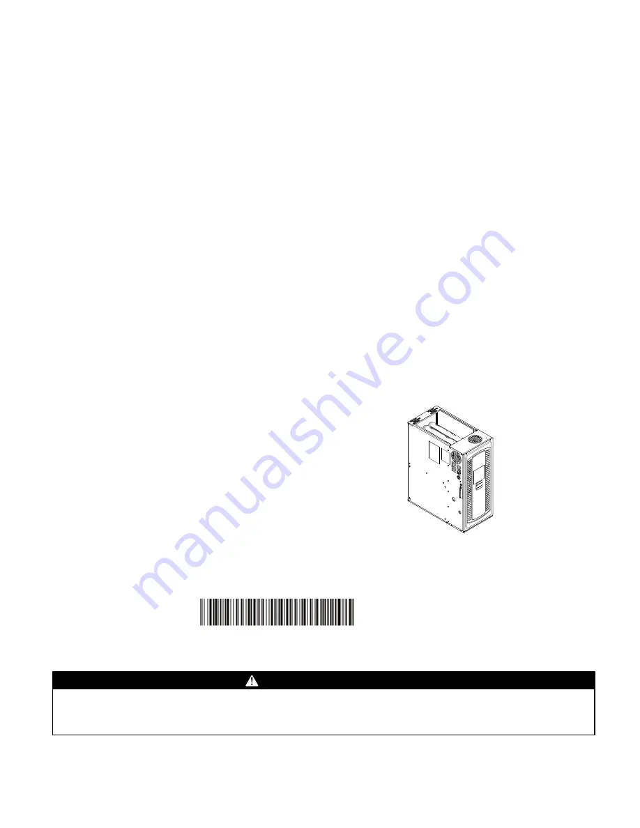
Upflow/Downflow/Horizontal Left/Right
Gas-Fired, Single Stage Induced Draft Furnaces with High
Efficiency Motor

U

Up

pffllo

ow

w,, D

Do

ow

wn

nffllo

ow

w,, H

Ho

orriizzo

on

ntta

all R

Riig

gh

htt//L

Le

efftt

Single Stage
S8B1A026M2PSAB
S8B1A040M3PSAB
S8B1B040M2PSAB
S8B1B060M3PSAB
S8B1B060M4PSAB
S8B1B080M4PSAB
S8B1C080M5PSAB
S8B1C100M5PSAB
S8B1D120M5PSAB

N

No

otte

e:: This installer’s Guide is used for multiple furnace families. Models

may have a “T” in the 12th digit designating they meet California less
than 40 ng/J (NOx) emissions requirements.

N

No

otte

e:: Graphics in this document are for

representation only. Actual model may

differ in appearance.

18-CE09D1-1E-EN

Installer’s Guide

Summary of Contents for S8B1A026M2PSAB

Page 1: ...0 1 18 8 C CE E0 09 9D D1 1 1 1E E E EN N Upflow Downflow Horizontal Left Right Gas Fired Single Stage Induced Draft Furnaces with High Efficiency Motor U Up pf fl lo ow w D Do ow wn nf fl lo ow w H Ho or ri iz zo on nt ta al l R Ri ig gh ht t L Le ef ft t Single Stage S8B1A026M2PSAB S8B1A040M3PSAB S8B1B040M2PSAB S8B1B060M3PSAB S8B1B060M4PSAB S8B1B080M4PSAB S8B1C080M5PSAB S8B1C100M5PSAB S8B1D120M5...

Page 2: ...E EC CT TR RI IC CA AL L S SH HO OC CK K F FI IR RE E O OR R E EX XP PL LO OS SI IO ON N H HA AZ ZA AR RD D F Fa ai il lu ur re e t to o f fo ol ll lo ow w t th hi is s W Wa ar rn ni in ng g c co ou ul ld d r re es su ul lt t i in n d da an ng ge er ro ou us s o op pe er ra at ti io on n p pr ro op pe er rt ty y d da am ma ag ge e s se ev ve er re e p pe er rs so on na al l i in nj ju ur ry y o or...

Page 3: ... pe er rs so on na al l i in nj ju ur ry y o or r d de ea at th h D Do o N NO OT T a at tt te em mp pt t t to o m ma an nu ua al ll ly y l li ig gh ht t t th he e f fu ur rn na ac ce e W WA AR RN NI IN NG G C CA AR RB BO ON N M MO ON NO OX XI ID DE E P PO OI IS SO ON NI IN NG G H HA AZ ZA AR RD D F Fa ai il lu ur re e t to o f fo ol ll lo ow w t th hi is s W Wa ar rn ni in ng g c co ou ul ld d r r...

Page 4: ...f f b be ef fo or re e s se er rv vi ic ci in ng g f fi il lt te er rs s t to o a av vo oi id d c co on nt ta ac ct t w wi it th h m mo ov vi in ng g p pa ar rt ts s W WA AR RN NI IN NG G C CA AR RB BO ON N M MO ON NO OX XI ID DE E H HA AZ ZA AR RD D F Fa ai il lu ur re e t to o f fo ol ll lo ow w t th hi is s W Wa ar rn ni in ng g c co ou ul ld d r re es su ul lt t i in n p pr ro op pe er rt ty y...

Page 5: ...a an n e ex xt te er rn na al l o ov ve er rf fl lo ow w d dr ra ai in n p pa an n b be e i in ns st ta al ll le ed d i in n a al ll l a ap pp pl li ic ca at ti io on ns s o ov ve er r a a f fi in ni is sh he ed d c ce ei il li in ng g t to o p pr re ev ve en nt t p pr ro op pe er rt ty y d da am ma ag ge e o or r p pe er rs so on na al l i in nj ju ur ry y f fr ro om m l le ea ak ki in ng g c co ...

Page 6: ...o ow ws s b be et tw we ee en n t th he e s sp pa ac ce e i in n w wh hi ic ch h t th he e a ap pp pl li ia an nc ce e s s c co on nn ne ec ct te ed d t to o t th he e v ve en nt ti in ng g s sy ys st te em m a ar re e l lo oc ca at te ed d A Al ls so o c cl lo os se e f fi ir re ep pl la ac ce e d da am mp pe er rs s T Tu ur rn n o on n c cl lo ot th he es s d dr ry ye er rs s a an nd d a an ny y...

Page 7: ...lve Adjustment 21 High Altitude Derate 22 General Venting 24 Air for Combustion and Ventilation 26 Duct Connections 29 Return Air Filters 39 Electrical Connections 41 Field Wiring 41 Twinning 42 General Start up and Adjustment 43 Preliminary Inspections 43 Lighting Instructions 43 Control and Safety Switch Adjustment 43 Furnace Combustion Air Exhaust Options 44 Combustion Air Conversions 47 Integr...

Page 8: ...00 CFM requires dual returns Document Pack Contents Item Qty Description S SA AF FE ET TY Y W WA AR RN NI IN NG G Only qualified personnel should install and service the equipment The installation starting up and servicing of heating ventilating and air conditioning equipment can be hazardous and requires specific knowledge and training Improperly installed adjusted or altered equipment by an unqu...

Page 9: ...and 80 Fahrenheit 80 models 55 F 90 models 45 F h Clean the Furnace duct work and components upon substantial completion of the construction process and verify Furnace operating conditions including ignition input rate temperature rise and venting according to the manufacturer s instructions 10 I In n t th he e C Co om mm mo on nw we ea al lt th h o of f M Ma as ss sa ac ch hu us se et tt ts s t t...

Page 10: ...the location selected as near the chimney or vent and as centralized for heat distribution as practical 2 Do all clearances between the Furnace and enclosure equal or exceed the minimums stated in Clearance Table below Minimum clearance to combustible materials 3 Is there sufficient space for servicing the Furnace and other equipment A minimum of 24 inches front accessibility to the Furnace must b...

Page 11: ...rom vehicles 9 The gas furnace must not be located where excessive exposure to contaminated combustion air will result in safety and performance related problems Avoid the following known contaminants a Permanent wave solutions b Chlorinated waxes and cleaners c Chlorine based swimming pool chemicals d Water softening chemicals e De icing salts or chemicals f Carbon tetrachloride g Halogen type re...

Page 12: ...12 18 CE09D1 1E EN Outline Drawings Table 2 14 5 Width Cabinet ...

Page 13: ...18 CE09D1 1E EN 13 Table 3 17 5 Width Cabinet O Ou ut tl li in ne e D Dr ra aw wi in ng gs s ...

Page 14: ...14 18 CE09D1 1E EN Table 4 21 Width Cabinet O Ou ut tl li in ne e D Dr ra aw wi in ng gs s ...

Page 15: ...18 CE09D1 1E EN 15 Table 5 24 5 Width Cabinet O Ou ut tl li in ne e D Dr ra aw wi in ng gs s ...

Page 16: ...allation in an attic should be on a service platform large enough to allow for proper clearances on all sides and service access to the front of the furnace See the Locations and Clearances p 10 Line contact is only permissible between lines formed by intersections of the top and two sides of the furnace casing and building joists studs or framing The furnace may be placed horizontally in a crawl ...

Page 17: ...ht side of the furnace in the upflow orientation Automatic Gas Valve with Manual Shut off Main Manual Shut off Valve Ground Union Joint Drip Leg 1 8 NPT Test Fitting Furnace in downflow orientation with gas piping on left Note For ease of installation optional accessory part PIP02095 is recommended for gas piping entering the left side of the furnace in the downflow orientation Automatic Gas Valve...

Page 18: ...ping out bottom Automatic Gas Valve with Manual Shut off Main Manual Shut off Valve Ground Union Joint Drip Leg 1 8 NPT Test Fitting Furnace in horizontal right orientation with gas piping out top Automatic Gas Valve with Manual Shut off Main Manual Shut off Valve Ground Union Joint Drip Leg 1 8 NPT Test Fitting Furnace in horizontal right orientation with gas piping out bottom Note For ease of in...

Page 19: ...l shut off valve during any pressure testing of the gas supply piping system at test pressures equal to or less than 1 2 psig 3 5 kPa Note Maximum pressure to the gas valve for natural gas is 13 8 W C Minimum pressure is 5 0 W C Maximum pressure to the gas valve for propane is 13 8 W C Minimum pressure is 11 0 W C NATURAL GAS ONLY TABLE OF CUBIC FEET PER HOUR OF GAS FOR VARIOUS PIPE SIZES AND LENG...

Page 20: ... utility company and compare to the nameplate rating This must not exceed the nameplate rating Gas Flow in Cubic Feet Per Hour 2 Cubic Foot Dial Sec Flow Sec Flow Sec Flow Sec Flow 10 732 31 236 52 141 86 85 11 666 32 229 53 138 88 83 12 610 33 222 54 136 90 81 13 563 34 215 55 133 94 78 14 523 35 209 56 131 98 75 15 488 36 203 57 128 100 73 16 458 37 198 58 126 104 70 17 431 38 193 59 124 108 68 ...

Page 21: ...e shown on manometer matches the pressure specified in the table The input of no more than nameplate rating and no less than 93 of the nameplate rating unless the unit is derated for high altitude d Replace and tighten the regulator cover screw securely 6 Cycle the valve several times to verify regulator setting a Repeat steps 5 6 if needed 7 Turn off all electrical power to the system 8 Remove th...

Page 22: ...thin the unit to the OFF position Turn the external gas valve to ON Purge the air from the gas lines After purging check all gas connections for leaks with a soapy solution DO NOT CHECK WITH AN OPEN FLAME Allow 5 minutes for any gas that might have escaped to dissipate Propane Gas being heavier than air may require forced ventilation Turn the toggle switch on the Gas Valve in the unit to the ON po...

Page 23: ...WC S8B1B040M2P BAYSWT21AHALTAA NA 0 47 0 05 WC S8B1B060M3P BAYSWT15AHALTAA NA 0 60 0 05 WC S8B1B060M4P BAYSWT15AHALTAA NA 0 60 0 05 WC S8B1B080M4P BAYSWT15AHALTAA NA 0 60 0 05 WC S8B1C080M5P BAYSWT14AHALTAB NA 0 50 0 05 WC S8B1C100M5P BAYSWT14AHALTAB NA 0 50 0 05 WC S8B1D120M5P BAYSWT14AHALTAB NA 0 50 0 05 WC F Fu ur rn na ac ce e G Ge en ne er ra al l I In ns st ta al ll la at ti io on n ...

Page 24: ...INTERNAL MASONRY CHIMNEYS Venting of fan assisted appliances into a lined internal masonry chimney is allowed only if it is common vented with at least one natural draft appliance OR if the chimney is lined with type B double wall vent or suitable flexible liner material W WA AR RN NI IN NG G S Sa af fe et ty y H Ha az za ar rd d F Fa ai il lu ur re e t to o f fo ol ll lo ow w t th hi is s w wa ar...

Page 25: ...n of the National Fuel Gas Code ANSI Z223 1 latest edition 10 Vent connectors serving appliance vented by natural draft or non positive pressure shall not be connected into any portion of a mechanized draft system operating under positive pressure 11 Horizontal pipe runs must be supported by hangers straps or other suitable material in intervals at a minimum of every 3 feet of pipe 12 A furnace sh...

Page 26: ...t be considered to avoid unsatisfactory Furnace operation Furnace location may be in an unconfined space or a confined space Unconfined space are installations with 50 cu ft or more per 1000 BTU hr input from all equipment installed Unconfined spaces are defined in the table and illustration for various furnace sizes These spaces may have adequate air by infiltration to provide air for combustion ...

Page 27: ...warranties are not available in some instances Extended warranty does not cover repairs to equipment installed in establishments with corrosive atmospheres including but not limited to dry cleaners beauty shops and printing facilities Minimum Free Area in Square Inches Each Opening Furnace Only in a Confined Space Furnace Max BTUH Input Rtg Air From Inside Air From Outside Vertical Duct a Horizont...

Page 28: ...te with the outdoors Refer to the Minimum Free Area in square inches for confined spaces table for minimum open areas required CONFINED SPACE AIR FROM OUTDOORS CONFINED SPACE OUTLET OUTDOOR AIR DUCTS INLET CONFINED SPACE AIR FROM VENTILATED ATTIC CRAWL SPACE CONFINED SPACE ALTERNATE INLET AIR INLET AIR DUCT OUTLET AIR ATTIC LOUVERS TO OUTDOORS CONFINED SPACE AIR FROM VENTILATED ATTIC CONFINED SPAC...

Page 29: ...naces not equipped with a cooling coil it is recommended that the outlet duct be provided with a removable access panel The opening shall be accessible when the furnace is installed and shall be of such a size that the heat exchanger can be viewed for possible openings using light assistance or a probe can be inserted for sampling the air stream The removable cover must be sealed to prevent air le...

Page 30: ...holes located on the furnace flange 4 Seal per local codes and requirements Furnace in Horizontal Left with Coil 1 Bend furnace flanges up 2 Support the furnace and coil independently 3 Screw through the coil cabinet into the furnace flange Guide holes are located on the coil Note There are no longer guide holes located on the furnace flange 4 Seal per local codes and requirements F Fu ur rn na ac...

Page 31: ...ace 4 Seal per local codes and requirements Note Flat or dedicated horizontal coils may require flanges to be bent upward Downflow Furnace with Coil 1 Bend furnace flanges down 2 Set the furnace on top of the coil so that it is flush with the back of the furnace 3 Seal per local codes and requirements F Fu ur rn na ac ce e G Ge en ne er ra al l I In ns st ta al ll la at ti io on n ...

Page 32: ...e no Coil Important A BAYBASE is required when installing the furnace on a combustible floor 1 Bend furnace flanges up 2 Attach ducting 3 Seal per local codes and requirements F Fu ur rn na ac ce e G Ge en ne er ra al l I In ns st ta al ll la at ti io on n ...

Page 33: ...ly An external overflow drain pan must be installed in all applications over a finished ceiling to prevent property damage Upflow Furnace with Bottom Return in Closet with Remote Filter 1 Remove the bottom plate 2 Set the furnace on the base inside closet 3 Install remote filter 4 Seal per local codes and requirements Upflow Furnace with Bottom Return in Closet with Filter Box 1 Remove the bottom ...

Page 34: ...from a remote location 3 Install filter at a remote location 4 Seal per local codes and requirements Upflow Furnace with Bottom Return Mounted on a Ducted Pedestal with Filter Box 1 Remove the bottom plate 2 Set the furnace on the filter box The ducted pedestal will use ducted air from a remote location 3 Seal per local codes and requirements FILTER F Fu ur rn na ac ce e G Ge en ne er ra al l I In...

Page 35: ...Note The furnace bottom pedestal must be a minimum of 6 in height 3 Match the filter cabinet flush to the back and bottom sides of the furnace cabinet and secure in place with screws 4 Mark the two areas to be cut out for the return air 5 Cut out the two sections of the cabinet and BAYLIFT kit to be removed 6 Attach ducting to the filter box 7 The ducted pedestal will use ducted air from a remote ...

Page 36: ...eturns Important One of the sides must have a transition to allow the thermostat wiring to exit the cabinet Important If a transition is not a viable option a hole will need to be drilled in the side of the cabinet for the thermostat wiring to exit Important Make sure not to cut the cabinet in the No Cut area Note If using one transition the thermostat wiring will exit on the transition side 1 Usi...

Page 37: ...op of the furnace 3 Install remote filter 4 Seal per local codes and requirements Downflow Furnace with Top Return and Plenum 1 Remove the top plate 2 Attach the plenum ducting to the top of the furnace 3 Install remote filter 4 Seal per local codes and requirements F Fu ur rn na ac ce e G Ge en ne er ra al l I In ns st ta al ll la at ti io on n ...

Page 38: ...w Furnace with Top Return and Plenum with Filter Box 1 Remove the top plate 2 Attach the filter box to the top of the furnace 3 Attach ducting 4 Seal per local codes and requirements FILTER F Fu ur rn na ac ce e G Ge en ne er ra al l I In ns st ta al ll la at ti io on n ...

Page 39: ...r Installations All return air duct systems should provide for installation of return air filters 1 Determine the appropriate position to set the furnace in order to connect to existing supply and return ductwork 2 For upflow side return installations remove the insulation around the opening in the blower compartment 3 The side panels of the upflow furnace include locating notches that are used as...

Page 40: ...cts to the furnace If only the front of the furnace is accessible it is recommended that both supply and return air plenums are removable 3 When replacing a furnace old duct work should be cleaned out Thin cloths should be placed over the registers and the furnace fan should be run for 10 minutes Don t forget to remove the cloths before you start the furnace 4 The horizontal installation of the up...

Page 41: ...ted furnace control is polarity sensitive The hot leg of the 120V power supply must be connected to the black power lead as indicated on the wiring diagram Refer to the SERVICE FACTS literature and unit wiring diagram attached to furnace Field Wiring O Y2 Y1 Y1 B B W1 W1 G G R R Y1 Two Stage Thermostat Furnace Outdoor Unit No Transformer O R X2 NOTES 1 HP Wiring used for Heat Pump systems 2 Y1 mus...

Page 42: ...FURNACES TWINNING CONNECTION DIAGRAM 1 STAGE HEAT 1 STAGE COOLING WITH TRANSFORMER THERMOSTAT 1 STAGE HEATING 1 STAGE COOLING THERMOSTAT FURNACE NO 1 FURNACE NO 2 ISOLATION RELAY FIELD SUPPLIED ISOLATION RELAY R1 R1 Y1 B Y1 Y1 Y1 W1 W1 W1 R R R G G G B B B NOTES 1 BOTH FURNACES MUST BE POWERED FROM THE SAME 115 VAC PHASE LEG AT THE CIRCUIT BREAKER 2 TRANSFORMERS MUST BE IN PHASE MEASURE THE VOLTAG...

Page 43: ...he e f fu ur rn na ac ce e To shut off For complete shutdown Turn the toggle or control switch located on the main gas valve inside the unit to the OFF position and the external main gas shutoff valve to the OFF position Disconnect the electrical supply to the unit Whenever your house is to be vacant arrange to have someone inspect your house for proper temperature This is very important during fr...

Page 44: ...ta an nt t When looking at the different orientations the direction of the combustion air exhaust in the illustration s description is after the furnace has been rotated if needed Table 9 Venting Options for Upflow Applications Refer to the illustrations below to find the approved venting options for upflow furnace Important The exhaust must be vented to the outdoors Upflow Orientation or Installa...

Page 45: ...r Installation Vented out top Vented through left side Table 11 Venting Options for Horizontal Right Applications Refer to the illustrations below to find the approved venting options for horizontal right furnace Important The exhaust must be vented to the outdoors Horizontal Right Orientation or Installation Vented out top Vented through right side F Fu ur rn na ac ce e C Co om mb bu us st ti io ...

Page 46: ...s Downflow Orientation or Installation Vented out top Note Requires kit BAYVENT600 Kit used with B C and D cabinets only Note A cabinet furnaces must be vented through the left of right side openings Note 4 Type B double wall vent pipe must be used inside of the furnace cabinet Vented through left side Vented through right side F Fu ur rn na ac ce e C Co om mb bu us st ti io on n A Ai ir r E Ex xh...

Page 47: ... the furnace in upflow position with the combustion air vented out the left side Note When rotating the inducer it may be necessary to cut the wire tie A new wire tie must be installed once the inducer is rotated 1 Remove the four screws holding the inducer in place 2 Rotate the inducer so the inducer outlet is pointing towards the 5 cutout 3 Secure the inducer in place using the screws removed in...

Page 48: ...vented out the left side 1 Remove the four screws holding the inducer in place 2 Rotate the inducer so the inducer outlet is pointing towards the 5 cutout 3 Secure the inducer in place using the screws removed in step 1 4 Attach the vent to the inducer outlet Note Self tapping screws are recommended for attaching the vent pipe to the inducer outlet Horizontal right orientation with right side vent...

Page 49: ...e recommended for attaching the vent pipe to the inducer outlet Downflow orientation with left side venting Before proceeding lay unit on its back to make the conversion easier The following changes need to be made to the inducer when installing the furnace in upflow position with the combustion air vented out the left side 1 Remove the four screws holding the inducer in place 2 Rotate the inducer...

Page 50: ...h top venting Before proceeding lay unit on its back to make the conversion easier The following changes need to be made to the inducer when installing the furnace in upflow position with the combustion air vented out the left side Note Requires kit BAYVENT600 Kit used with B C and D cabinets only Follow kit instructions for installation Note 4 Type B double wall vent pipe must be used inside of t...

Page 51: ... the OPTION key to the desired se ng Then momentarily depress the MENU key again to save the change 180 C1 7 C1 1 C1 2 C1 3 C1 4 HtP Hea ng Speed Tap H1 5 H1 1 01 H1 2 H1 6 H1 3 Example Single Stage run Run Test Mode C1 5 C1 6 C1 8 C1 9 H1_7 H1 8 H1 4 ORN LED Orienta on UP dn Default Airflow Taps Gas Heat Tap 5 ODU Menu 1 1 Cooling HP Tap 7 ODU 2 1 not applicable to S8B1 Do Not adjust from 1 1 Des...

Page 52: ...ode momentarily push the Menu key cycle power to the furnace or make a valid thermostat call for capacity or fan Sequence of Run Test Mode Turns the inducer on in 1st stage for 30 seconds Turns on the inducer on 2nd stage for 30 seconds Not applicable on S8B1 Turns the ignitor on for 10 seconds Turns the circula ng blower on 1st stage compressor speed for 10 seconds Turns the circula ng blower on ...

Page 53: ...to watch a short video Evaporator Coil Clean Filter Furnace Airflow CFM Vs External Static Pressure in W C Model Tap 0 1 0 3 0 5 0 7 0 9 S8B1B080M4PSAB 1 633 297 2 957 800 719 428 213 3 1220 1080 940 800 660 4 1403 1298 1192 1087 981 5 1524 1428 1336 1248 1164 6 1684 1574 1544 1401 1337 7 1700 1625 1551 1476 1401 8 1858 1790 1723 1656 1589 9 1967 1898 1829 1760 1691 E Ex xa am mp pl le e 1 1 S S8 ...

Page 54: ...rnal failures Internal IFC error e2 Retry Exceeded Flame never sensed one hour lockout after 3 times e2 2 Recycles Exceeded Flame sensed then lost one hour lockout after 10 times e2 3 1st Stage Gas Valve Not Energized When It Should Be exceeded after 10 times e3 Shorted Pressure Switch e3 2 Open Pressure Switch e04 Open Limit Main Thermal Rollout Switch or Reverse Airflow Switch e0s Flame detected...

Page 55: ...actory Defaults 1 Display must be in Idle Mode 2 Push the Menu and Option buttons at the same time for 15 seconds then release 3 The 7 segment will flash FD 3 times This confirms the unit has been reset to the factory defaults Low Voltage Terminal Strip 10 Pin Connector ILI not used LINE Connections Neutral Connections 7 Segment LED MENU and OPTION Select Buttons 5 Amp Fuse Flame Current FP HLI W ...

Page 56: ...current use a VOM set to DC volts 1VDC 1 micro amp Flame current will vary depending on the type of meter used Typical flame current ranges from 0 75 3 0 micro amps 0 75 3 VDC 8 Once the flame sense has been established a timer on the IFC starts and the indoor blower will energize after the blower Heat On Delay has completed The seven segment LED for example will alternately read Xt Gas heating tP...

Page 57: ...18 CE09D1 1E EN 57 N No ot te es s ...

Page 58: ...58 18 CE09D1 1E EN N No ot te es s ...

Page 59: ...18 CE09D1 1E EN 59 N No ot te es s ...

Page 60: ...lications For more information please visit www trane com or www americanstandardair com The manufacturer has a policy of continuous data improvement and it reserves the right to change design and specifications without notice We are committed to using environmentally conscious print practices 18 CE09D1 1E EN 06 May 2020 Supersedes 18 CE09D1 1D EN December 2019 2020 ...

Reviews: