background image

508142-01

Issue 2047

Page 6 of 33

BL

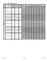
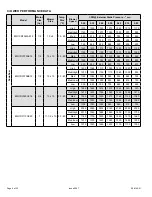
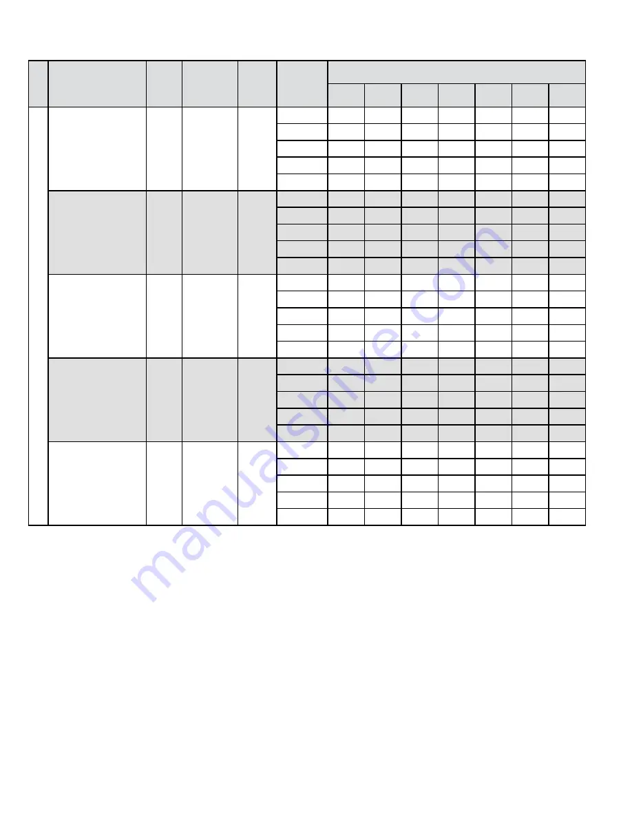
OWER PERFORMANCE DATA  

Model

Motor 

Size 

(hp)

Blower 

Size

Temp 

Rise 

(°F)

Blower 

Speed

CFM @ External Static Pressure - " w.c.

0.20

0.30

0.40

0.50

0.60

0.70

0.80

Downflow

80G10DF045AE12

1/2

10 x 8

15 - 45

High

1375

1335

1320

1275

1245

1215

1175

Med/High

1145

1120

1075

1045

1000

970

925

Med 

950

915

870

835

785

745

695

Med/Low

840

790

745

715

655

605

555

Low 

725

665

625

565

520

455

400

80G1DF070AE12

1/2

10 x 10

30 - 60

High

1420

1400

1375

1340

1285

1210

1140

Med/High

1195

1180

1150

1120

1075

1065

1020

Med 

1115

1070

1045

1010

985

955

920

Med/Low

1090

1055

1025

990

955

915

890

Low 

920

900

845

820

770

730

675

80G1DF070BE12

1/2

10 x 10

30 - 60

High

1400

1360

1310

1280

1250

1220

1165

Med/High

1230

1205

1155

1110

1060

1000

935

Med 

1125

1085

1050

985

935

865

795

Med/Low

1110

1055

1000

950

865

815

750

Low 

900

845

790

705

645

590

480

80G1DF090CE16

3/4

10 x 10

30 - 60

High

1695

1660

1615

1570

1545

N/A

N/A

Med/High

1470

1425

1395

1360

1295

1265

1215

Med 

1340

1290

1250

1210

1165

1120

1080

Med/Low

1280

1225

1185

1145

1085

1040

1000

Low 

1105

1040

1005

945

865

810

755

80G1DF110CE20

1

11-1/2 x 10

30 - 60

High

2325

2280

2235

2165

2125

2090

2035

Med/High

2010

1940

1895

1845

1800

1755

1700

Med 

1760

1705

1635

1595

1545

1510

1460

Med/Low

1570

1500

1440

1380

1320

1285

1255

Low 

1375

1320

1265

1200

1170

1100

1030

Summary of Contents for 80G1DFE

Page 1: ...symbol and should never be ignored When you see this symbol on labels or in manuals be alert to the potential for personal injury or death Electric shock hazard Can cause injury or death Before attempting to perform any service or maintenance turn the electrical power to unit OFF at disconnect switch es Unit may have multiple power supplies WARNING As with any mechanical equipment contact with sha...

Page 2: ...el Input Btuh Output Btuh AFUE ICS Nom Cooling Capacity Gas Inlet in Volts Hz Phase Max Time Delay Breaker or Fuse Nominal F L A Trans V A Approx Shipping Weight lbs Downflow A80DF1E045A12 44 000 36 000 80 00 2 3 1 2 120 60 1 15 6 8 40 113 A80DF1E070A12 66 000 54 000 80 00 2 3 1 2 120 60 1 15 6 8 40 119 A80DF1E070B12 66 000 54 000 80 00 2 3 1 2 120 60 1 15 6 8 40 128 A80DF1E090B16 88 000 72 000 80...

Page 3: ...ed Low 1090 1055 1025 990 955 915 890 Low 920 900 845 820 770 730 675 A80DF1E070B12 1 2 10 x 10 30 60 High 1400 1360 1310 1280 1250 1220 1165 Med High 1230 1205 1155 1110 1060 1000 935 Med 1125 1085 1050 985 935 865 795 Med Low 1110 1055 1000 950 865 815 750 Low 900 845 790 705 645 590 480 A80DF1E090B16 3 4 10 x 10 30 60 High 1695 1660 1615 1570 1545 N A N A Med High 1470 1425 1395 1360 1295 1265 ...

Page 4: ... A Width 68W62 17 5 B Width 68W63 21 0 C Width 68W64 24 5 D Width Downflow Combustible Flooring Base 11M59 14 5 A Width 11M60 17 5 B Width 11M61 21 0 C Width Night Service Kit 86W57 Single Stage Horizontal Suspension Kit 51W10 80 90 Kit 2 Stage Compressor Relay Kit 85W66 Blower Relay Kit Twinning Kit 16W72 Constant Torque Gas Furnace Twinning Kit Note For vent length and clearances to combustibles...

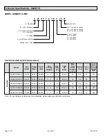
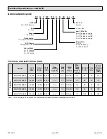
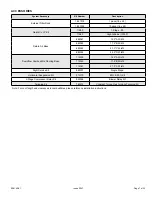
Page 5: ...G 1 D F 110 C E 20 L 01 PHYSICAL AND ELECTRICAL DATA Model Input Btuh Output Btuh AFUE ICS Nom Cooling Capacity Gas Inlet in Volts Hz Phase Max Time Delay Breaker or Fuse Nominal F L A Trans V A Approx Shipping Weight lbs Downflow 80G1DF045AE12 44 000 36 000 80 00 2 3 1 2 120 60 1 15 6 8 40 113 80G1DF070AE12 66 000 54 000 80 00 2 3 1 2 120 60 1 15 6 8 40 119 80G1DF070BE12 66 000 54 000 80 00 2 3 1...

Page 6: ...ed Low 1090 1055 1025 990 955 915 890 Low 920 900 845 820 770 730 675 80G1DF070BE12 1 2 10 x 10 30 60 High 1400 1360 1310 1280 1250 1220 1165 Med High 1230 1205 1155 1110 1060 1000 935 Med 1125 1085 1050 985 935 865 795 Med Low 1110 1055 1000 950 865 815 750 Low 900 845 790 705 645 590 480 80G1DF090CE16 3 4 10 x 10 30 60 High 1695 1660 1615 1570 1545 N A N A Med High 1470 1425 1395 1360 1295 1265 ...

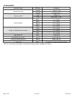
Page 7: ... A Width 68W62 17 5 B Width 68W63 21 0 C Width 68W64 24 5 D Width Downflow Combustible Flooring Base 11M59 14 5 A Width 11M60 17 5 B Width 11M61 21 0 C Width Night Service Kit 86W57 Single Stage Horizontal Suspension Kit 51W10 80 90 Kit 2 Stage Compressor Relay Kit 85W66 Blower Relay Kit Twinning Kit 16W72 Constant Torque Gas Furnace Twinning Kit Note For vent length and clearances to combustibles...

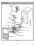
Page 8: ...e 8 of 33 Parts Arrangement Figure 1 BLOWER ASSEMBLY CABINET CONTROL BOX INTERNAL FLUE PIPE ASSEMBLY FLUE CHASE HEAT EXCHANGER GAS VALVE ACCESS PANEL BURNER BOX ASSEMBLY COMBUSTION AIR INDUCER ROLLOUT LOCATED INSIDE BURNER BOX ...

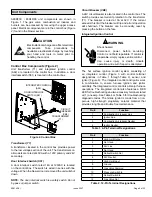
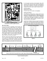
Page 9: ...ovides overcurrent protection to the transformer T1 The breaker is rated at 3A at 32V If the current exceeds this limit the breaker will trip and all unit operation will shutdown The breaker can be manually reset by pressing the button on the face Integrated Ignition Control Shock hazard Disconnect power before servicing Control is not field repairable If control is inoperable simply replace entir...

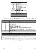
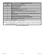
Page 10: ...g heat demand 4 Low Flame Signal check flame sensor 5 Watchguard burner failed to light exceeded maximum number of retries or recycles 6 Not Used 7 Primary or Secondary Limit Open or Watchguard Mode Limit Switch Open longer than 3 minutes 8 Rollout Switch Open 9 Pressure Switch failed to close or opened during heat demand 10 Watchguard Pressure Switch opened 5 times during one heat demand 11 Press...

Page 11: ... Open 9 Pressure Switch failed to close or opened during heat demand 10 Watchguard Pressure Switch opened 5 times during one heat demand 11 Pressure Switch stuck closed prior to activation of combustion air inducer 12 Flame Sensed without gas valve energized 13 Low Line Voltage 1 A Heartbeat is indicated by a Slow Flash 1 sec on 1 sec off repeating 2 Error codes are indicated by a Rapid Flash the ...

Page 12: ...warm up time between trials of 35 seconds After a total of five trials for ignition including the initial trial the integrated control goes into Watchguard Flame Failure mode After a 60 minute reset period the integrated control will begin the ignition sequence again Fan Time Control Heating Fan On Time The fan on time of 30 seconds is not adjustable Heating Fan Off Time Fan off time time that the...

Page 13: ...ut switch S47 is a high temperature limit Each furnace is equipped with two identical switches The limit is a N C SPST manual reset limit connected in series with the integrated control A92 When S47 senses rollout the integrated control immediately stops ignition and closes the gas valve If unit is running and flame rollout is detected the gas valve will close and integrated control will be disabl...

Page 14: ...l number Gas Valve Figure 6 The A95UH1E 95G1UHE uses an internally redundant valve to assure safety shut off If the gas valve must be replaced the same type valve must be used 24VAC terminals and valve switch are located on the valve All terminals on the gas valve are connected to wires from the integrated control 24V applied to the terminals energizes the valve Inlet and outlet pressure taps are ...

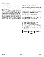
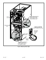
Page 15: ... Sensor Wire from Integrated Control and Connect Alligator Clip to Flame Sensor Lead Flame Sensor Terminal Remove Sensor Wire from Integrated Control and Connect Alligator Clip to Terminal on Control DIGITAL METER To Control Sensor Terminal To flame sensor Set dial to measure dc microamps Red Collar Indicates Positive Lead ...

Page 16: ...eck resistance of ignitor at the plug Reading should be between 39 and 70 ohms If the reading is correct then the problem is with the wiring between the jack plug and the control If reading is not correct the issue is the ignitor Test 3 Check ignitor for correct voltage Insert meter probes into terminals 2 and 4 use small diameter probes in order not to damage plug Check voltage during 20 second i...

Page 17: ...ucer housing The switch is a single pole single throw proving switch electrically connected to the furnace control The purpose of the switch is to prevent burner operation if the combustion air inducer is not operating or if the flue becomes obstructed On start up the switch senses that the combustion air inducer is operating It closes a circuit to the integrated control when pressure inside the c...

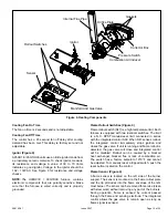
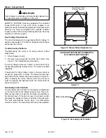
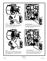
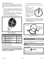
Page 18: ...sent in tests 1 and 2 and motor is not operating properly replace motor The motor is not field repairable If replacing the indoor blower motor or blower wheel is necessary placement is critical The blower wheel must be centered in the blower housing as shown in Figure 10 When replacing the indoor blower motor the set screw must be aligned and tightened with the motor shaft as shown in Figure 11 Se...

Page 19: ...g P49 If 24 volts is not present problem may be up stream of plug P49 Proceed to test 4 Multi Meter set to VAC 12 0 12 0 24 Multi Meter set to VAC problem is with the harness If voltage is not present problem may be may be with the integrated control Check for 120 volts across terminals CIRC and Neutrals on the integrated control If voltage is present problem is with the harness If voltage is not ...

Page 20: ...ules look similar however each module is designed for a specific motor size It is very important to make sure that you are using the correct replacement motor control module USE OF THE WRONG MOTOR CONTROL MODULE MAY RESULT IN UNEXPECTED UNIT OPERATION 1 Verify electrical power to unit is disconnected 2 Connect three wire harness from motor to control module 3 Mount new motor control module to moto...

Page 21: ...ce the upper access panel Safety or Emergency Shutdown Disconnect main power to unit Close manual and main gas valves Extended Period Shutdown Turn off thermostat or set to UNOCCUPIED mode Close all gas valves both internal and external to unit to guarantee no gas leaks into combustion chamber Turn off power to unit All access panels and covers must be in place and secured Heating System Service C...

Page 22: ...arbed fitting Connect to a test gauge to measure supply pressure 2 Start unit and allow 5 minutes for unit to reach steady state 3 After allowing unit to stabilize for 5 minutes record supply pressure and compare to value given in Table 10 Manifold Pressure Measurement 1 Remove the threaded plug from the outlet side of the gas valve and install a field provided barbed fitting Connect to a test gau...

Page 23: ...0 0625 3 5 No Change 0 0625 3 3 51W01 0 0550 3 5 LP Propane 11 0 13 0 11K50 0 034 10 0 11K50 0 034 10 0 11K50 0 034 10 0 11K45 0 032 10 0 090 Nat 4 5 10 0 No Change 0 0625 3 5 No Change 0 0625 3 5 No Change 0 0625 3 3 51W01 0 0550 3 5 LP Propane 11 0 13 0 11K50 0 034 10 0 11K50 0 034 10 0 11K50 0 034 10 0 11K45 0 032 10 0 110 Nat 4 5 10 0 No Change 0 0625 3 5 No Change 0 0625 3 5 No Change 0 0625 ...

Page 24: ... indicates a poor or partial ground Compare the readings to Table 11 If the readings exceed the maximum shown in Table 11 make repairs before operating the furnace 2 In addition measure the AC voltage from Line Hot to Line Neutral spade terminals on the integrated control See Figure 18 This voltage should be in the range of 97 to 132 VAC Furnace Status Measurement VAC Expected Maximum Power On Fur...

Page 25: ... hole in supply and return air plenums Insert manometer hose flush with inside edge of hole or insulation Seal around the hose with permagum Connect the zero end of the manometer to the discharge supply side of the system On ducted systems connect the other end of manometer to the return duct as above 3 With only the blower motor running and the evaporator coil dry observe the manometer reading Ad...

Page 26: ...if necessary 6 Check the cleanliness of blower assembly and clean the housing blower wheel and blower motor if necessary The blower motors are prelubricated for extended bearing life No further lubrication is needed 7 Inspect the combustion air inducer and clean if necessary 8 Evaluate the heat exchanger integrity by inspecting the heat exchanger per the AHRI heat exchanger inspection procedure Th...

Page 27: ...he left side or right side of cabinet See Figure 21 9 Back wash using steam Begin from the burner opening on each clam Steam must not exceed 275 F 10 To clean burners run a vacuum cleaner with a soft brush attachment over the face of burners Visually inspect inside the burners and crossovers for any blockage caused by foreign matter Remove any blockage Figure 22 shows burner detail 11 To clean the...

Page 28: ...n air inducer burners manifold and gas valve retention rings cross over heat exchanger gasket collector box orifice plate internal flue pipe pressure switch combustion air inducer burners manifold and gas valve flue chase gasket ignitor rollout switch sensor Figure 22 Burner Combustion Air Inducer Assembly Heat Exchanger Removal ...

Page 29: ...508142 01 Issue 2047 Page 29 of 33 Wiring Diagram Figure 23 ...

Page 30: ...GIZED GAS VALVE OFF COMBUSTION AIR INDUCER ON INDOOR BLOWER ON HEATING SPEED LED FLASHES CODE 11 PRESSURE SWITCH CLOSED GAS VALVE OFF COMBUSTION AIR INDUCER OFF INDOOR BLOWER OFF WITH DELAY Sequence holds until pressure switch opens or thermostat resets control NO NO YES YES IS VOLTAGE ABOVE 70 VOLTS LED FLASHES CODE 13 LOW LINE VOLTAGE CONTROL WILL NOT RESPOND TO A CALL FOR HEATING UNTIL VOLTAGE ...

Page 31: ...FF WITH DELAY IS 60 MINUTE RESET PERIOD COMPLETE YES 4 SECONDS YES HAS CONTROL RESET IGNITION SEQUENCE FOUR TIMES FLAME SIGNAL 1 5 MICROAMPS OR GREATER YES YES YES ROLLOUT SWITCH CLOSED LED FLASHES CODE 8 ROLLOUT SWITCH OPEN GAS VALVE POWER OFF COMBUSTION AIR INDUCER POWER ON INDOOR BLOWER ON SEQUENCE HOLDS UNTIL ROLLOUT SWITCH IS RESET AND MAIN POWER IS INTERRUPTED OR THERMOSTAT IS CYCLED OFF ON ...

Page 32: ...ONITORED CONTINUOUSLY IS ROLLOUT SWITCH CLOSED LED SLOW FLASH RATE REMAINS UNCHANGED THROUGHOUT COOLING CYCLE THERMOSTAT CALLS FOR COOLING COMPRESSOR CONTACTOR AND SYSTEM FAN ENERGIZED WITH 2 SECOND DELAY COOLING SPEED COMPRESSOR OFF THERMOSTAT OPENS SYSTEM FAN AND EAC TERM OFF WITH 45 SECOND DELAY NO NO LED FLASHES CODE 8 ROLLOUT SWITCH OPEN GAS VALVE OFF COMBUSTION AIR INDUCER ON INDOOR BLOWER O...

Page 33: ...G THERMOSTAT OPENS SYSTEM FAN SWITCHED TO COOL SPEED EAC TERM REMAINS ON THERMOSTAT OPENS MANUAL FAN SELECTION MADE AT THERMOSTAT CONTROL G ENERGIZES SYSTEM FAN AT FAN SPEED EAC TERM ENERGIZED NO YES YES NO SYSTEM FAN SWITCHES TO HEAT SPEAD AFTER 30 SECOND DELAY EAC AND HUM TERMINALS REMAIN ON SYSTEM FAN CONTINUES FAN SPEED WITHOUT INTERRUPTION EAC TERMINAL REMAIN ON HUM TERMINALS ARE ENERGIZED WI...

Reviews: