background image

8

Safety - 5010 & 6010 Snowblower

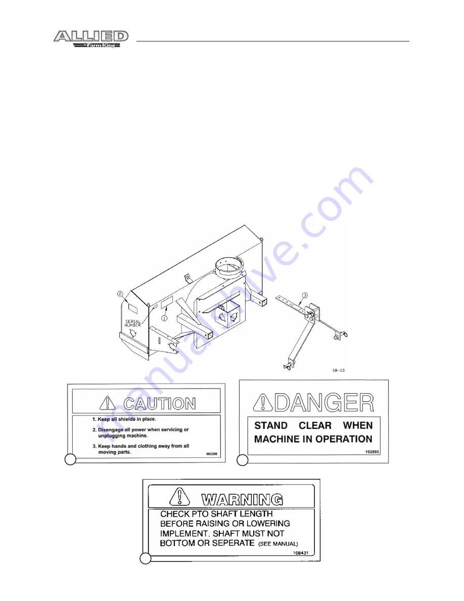
Safety Signs

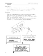
•  The following illustration shows the approximate location and detail of safety signs.
•  Keep all safety signs clean and legible and replace any that are damaged or missing.
•  When original parts are replaced, any safety signs affixed to those parts should be replaced 

as well. Replacement safety signs are available from your local dealer.

Installation

•  To install safety signs, ensure the installation area is clean and dry. Decide on the exact 

position before you remove the backing paper. Remove the smallest portion of the split 
backing paper and align over the specified area. Carefully press in place.

•  Slowly peel back the remaining paper and smooth the remaining portion in place. Small air 

pockets can be pierced with a pin and smoothed out.

•  Replace safety signs immediately should they become damaged, torn or illegible. Obtain 

replacements from your authorized dealer using the part numbers shown.

1

2

3

Summary of Contents for 5010

Page 1: ...Snowblower Models 5010 6010 OPERATOR AND PARTS MANUAL 102010 FK312 ...

Page 2: ......

Page 3: ...oltTorque 13 Parts Drawings 14 Snowblower Drawings 14 Snowblower Parts List 16 PTO Drawing 20 PTO Parts List 21 Cylinder Assembly Drawing and Parts List 22 Shipping Kit and Bundle Numbers 23 Warranty 24 Manufacturer s statement for technical reasons Buhler Industries Inc reserves the right to modify machinery design and specifications provided herein without any preliminary notice Information prov...

Page 4: ...l models A length adjustable hitch is standard on all models Also available is an optional Hydraulic Spout Control There is a shear bolt on the auger and on the PTO shaft to protect the machine from damage if a large object is picked up Any smaller objects in the snow will be thrown with it and could cause serious injury Do not allow anyone stand behind the tractor or in the area of the discharged...

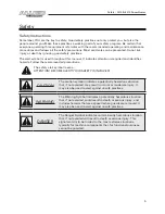
Page 5: ...mmended precautions The safety alert symbol means ATTENTION BECOME ALERT YOUR SAFETY IS INVOLVED CAUTION The caution symbol indicates a potentially hazardous situation that if not avoided may result in minor or moderate injury It may also be used to alert against unsafe practices WARNING The Warning Symbol indicates a potentially hazardous situation that if not avoided could result in death or ser...

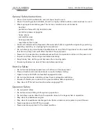
Page 6: ...ept from the operator s station on the power unit Inspect and clean the working area before operating Keep hands feet clothing and hair away from moving parts Ensure bystanders are clear of the area before operating Start Up Safety Do not let inexperienced operators or children run this equipment Place all tractor and machine controls in neutral before starting Operate only with ROPS and seatbelt ...

Page 7: ... stop before servicing adjusting repairing or unplugging Support the equipment with blocks or safety stands before working beneath it Follow good shop practices including keep service area clean and dry be sure electrical outlets and tools are properly grounded use adequate light for the job Use only tools jacks and hoists of sufficient capacity for the job Replace and secure all shields removed d...

Page 8: ...dealer Installation To install safety signs ensure the installation area is clean and dry Decide on the exact position before you remove the backing paper Remove the smallest portion of the split backing paper and align over the specified area Carefully press in place Slowly peel back the remaining paper and smooth the remaining portion in place Small air pockets can be pierced with a pin and smoo...

Page 9: ...sher and hex nut Use the same hole position as the hitch tubes Tighten all hardware A category 1 top link pin 8 is fitted in the top holes of the hitch arm plates This pin is used for standard three point hitch only The bushing in the lower holes is used for the quick hitch 3 Hand Crank Assembly Standard Bolt the crank mounting bracket 16 to the top of the hitch using 3 8 x 1 1 4 hex bolts lock wa...

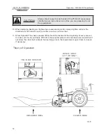
Page 10: ...rely attached every time the snowblower is used This should always be done with the tractor engine off Check that the PTO shaft does not bottom or separate with the blower in the extreme high and low positions Check to see which of the four different hitch positions will allow you to keep about a 4 minimum overlap on the PTO shields without bottoming out This position varies between different trac...

Page 11: ...ts to protect the tractor and blower in case a large object enters the blower PTO shear bolts 50 one 3 8 x 1 gr 8 60 two 5 16 x 1 gr 8 auger shear bolt 1 4 x 1 gr 2 Shear bolts should be fastened with a lock nut or two jam nuts These bolts must be kept tight to prevent wear of the bolt and bolt holes 6 Never run PTO shaft at over 600 rpm 7 ChainTension Slack on the lower side of the chain should b...

Page 12: ...ghten collar in the direction of shaft rotation using a center punch or a similar tool 11 Shear Sprocket The shear sprocket 43 should be checked at the beginning of every season to make sure it will spin freely With time the sprocket plate could corrode and seize which will not allow the shear bolt to break if something jams in the snowblower auger Clean to loosen if necessary Operation 5010 6010 ...

Page 13: ...t N m lb ft N m 0 25 1 4 6 8 9 12 12 17 0 313 5 16 10 13 19 25 27 36 0 375 3 8 20 27 33 45 45 63 0 438 7 16 30 42 53 72 75 100 0 5 1 2 45 61 80 110 115 155 0 563 9 16 70 95 115 155 165 220 0 625 5 8 95 128 160 215 220 305 75 3 4 165 225 290 390 400 540 0 875 7 8 170 230 420 570 650 880 1 225 345 630 850 970 1320 Torque figures indicated above are valid for non greased or non oiled threads and head...

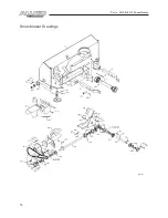
Page 14: ...14 Parts 5010 6010 Snowblower Snowblower Drawings ...

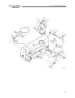
Page 15: ...15 Parts 5010 6010 Snowblower ...

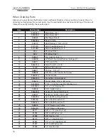
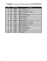
Page 16: ... Linch Pin 11 965624A Hitch Pin 3 4 x 3 1 4 12 12779 9 Hair Pin Clip pl 13 968811 Pto Key 1 4 x 2 14 988999 3 8 Dia x 3 8 Socket Set Screw 15 906667A Crank Handle 16 965634A Crank Mounting Bracket 17 965616 Crank Cable 3 16 x 84 Long 18 9812438 1 ID x 14 Ga Narrow Rim Washer pl 19 9812425 1 4 x 1 1 4 Spring Pin 20 965806 3 16 Cable Clamp 21 965626A Hydraulic Swivel Weldment 22 965627 Hydraulic Cab...

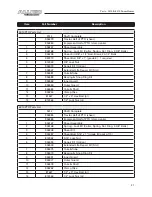
Page 17: ... 965632A Idler Spacer 1 2 Long 46 965069 Fan Shaft 1 1 4 x 14 1 2 47 961882 Bevel Gear 1 1 4 Bore 48 961676 1 1 4 Bearing w Collar 49 961675A 1 1 4 Bearing Retainer 50 901331 Fan Key 1 4 x 3 1 2 51 109343 3 16 x 1 1 8 Woodruff Key 52 84335 5 8 x 2 1 2 Hex Bolt pl 53 81678 5 8 Flat Washer BS pl 54 81677 5 8 Lock Washer pl 55 81676 5 8 Hex Nut pl 56 812216 1 4 x 1 Hex Bolt pl Gr 2 57 84498 1 4 Lock ...

Page 18: ...477 Skid Plate Weldment F6598 Skid Plate Bundle 78 812026 5 16 x 1 Hex Bolt pl 79 936402 PTO Safety Chain 80 9812487 Narrow Rim Washer 1 1 4 x 10ga pl 81 967110 Narrow Rim Washer 1 1 4 x 14ga pl 82 9812439 Narrow Rim Washer 1 1 4 x 18ga pl 83 907133A Hitch Arm Weldment L 84 907134A Hitch Arm Weldment R 85 907138A HitchTop Bar Weldment 50 907139A HitchTop Bar Weldment 60 86 84336 3 4 x 4 Hex Bolt p...

Page 19: ......

Page 20: ...20 Parts 5010 6010 Snowblower PTO Shaft Drawing ...

Page 21: ...ing Kit 9 936382 Inner Guard 10 936383 Outer Guard 11 936384 Yoke Shaft 12 936254 ClampYoke 13 81627 1 2 x 3 Hex Bolt pl 14 812364 1 2 Lock Nut pl 6010 PTO Parts List F612 Shaft Complete 936385 Tractor Half of PTO shear 936386 Implement Half of PTO clamp yoke 1 936167 Shear Assembly 2 936168 Spring Lock Kit Collar Spring Ret Ring 2 3 8 Balls 3 936248 Shear Kit 4 903297 Shear Bolt 5 16 x 1 grade 8 ...

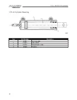
Page 22: ...22 Parts 5010 6010 Snowblower 1 75 x 5 Cylinder Drawing Item Part Number Description 24930 Cyl Complete 1 115367 Tube Weldt 2 112104 Shaft Weldt 1 0 Dia 3 X2669 Seal Kit ...

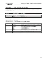
Page 23: ...Snowblower w Hand Crank 4 Blade Fan 1 F0437 Body Assembly Optional Bundle Numbers The following is a list of options available for the Kits listed above 1 FX9304 Hydraulic Chute Control for 5010 6010 Snowblowers Less Cylinder 1 FX9305 Hand Crank for 5010 6010 Snowblowers 1 F512 5010 Snowblower PTO 1 F612 6010 Snowblower PTO 1 F9117 Deflector Cylinder Hose Kit for 5010 6010 1 F621 Optional Long PTO...

Page 24: ... require replacement as part of normal maintenance Also Buckets and Bucket Tines carry no warranty Bent Spears carry no warranty Snowblower Fan Shafts carry no warranty Mower Blades carry no warranty Portable Auger Parts Have Two 2 Year Warranty Loader Parts Have Two 2 Year Warranty The purchaser is solely responsible for determining suitability of goods sold This warranty is expressly in lieu of ...

Page 25: ...nc Warranty Claim Forms with all requested information properly completed Warranty Claims must be submitted within a thirty 30 day period from date of failure repair Warranty Labor Any labor subject to warranty must be authorized by Buhler Industries Inc The labor rate for replacing defective parts where applicable will be credited at 100 of the dealer s posted shop rate Defective parts will recei...

Page 26: ...y or enlarge this limited warranty or its exclusions limitations and reservations Corrections of defects and improper workmanship in the manner and for the applicable time periods provided for herein shall constitute fulfillment of all responsibilities of Buhler Industries Inc to the purchaser and Buhler Industries Inc shall not be liable in negligence contract or on any other basis with respect t...

Page 27: ......
Page 28: ...stries Inc 1330 43rd Street NW Fargo ND USA 58102 Ph 701 282 7014 Fax 701 282 5865 Toll Free 888 524 1004 E mail info buhler com www farm king com Equipment shown is subject to change without notice 2010 BuhlerTrading Inc Printed in USA TSX BUI ...

Reviews: