background image

Display camera live images

How to install a GigE camera (Bigeye/Pearleye/Goldeye)


V2.1.0

24

Advanced operations

The AcquireControl software was developed for many different cameras.

This chapter introduces the basic commands for controlling your camera.

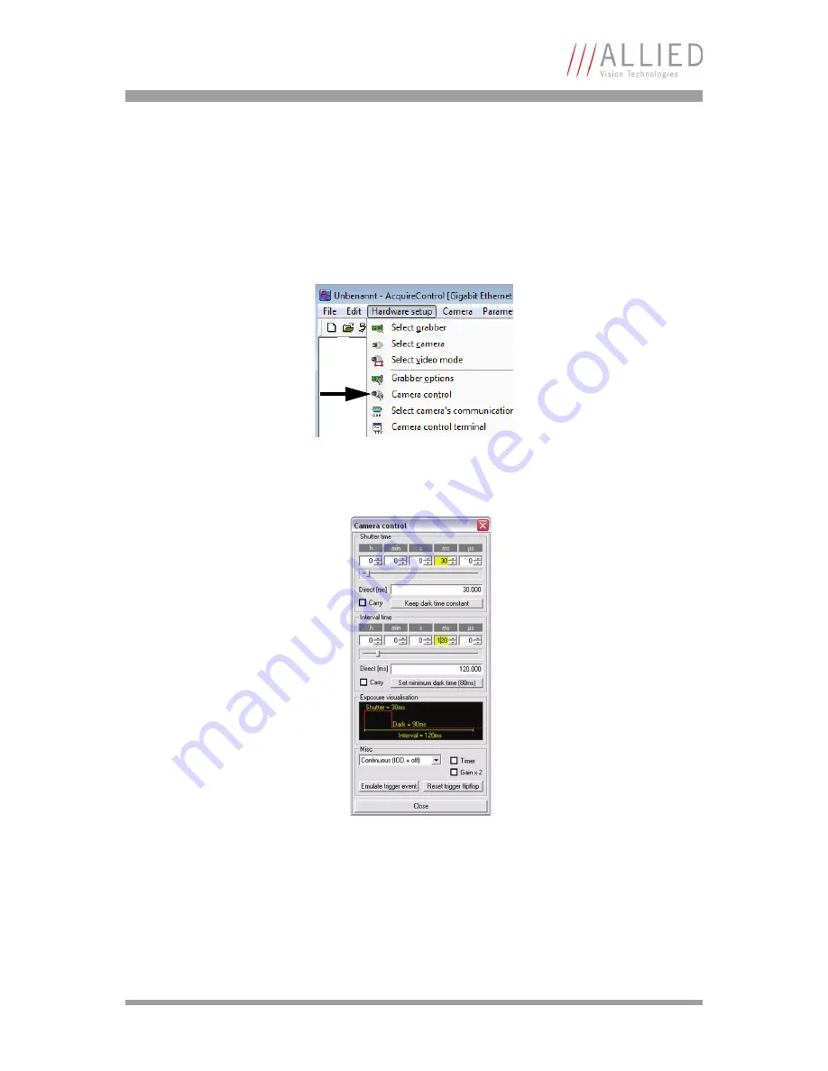
Exposure control

 Figure 14: Camera control

 Figure 15: Camera control: Exposure control

Summary of Contents for AVT GigE Bigeye

Page 1: ...How to install a GigE camera Bigeye Pearleye Goldeye V2 1 0 04 May 2012 Allied Vision Technologies GmbH Taschenweg 2a D 07646 Stadtroda Germany AVT GigE Bigeye Pearleye Goldeye ...

Page 2: ...or implicit Also excluded are all implicit warranties concern ing the negotiability the suitability for specific applications or the non breaking of laws and pat ents Even if we assume that the information supplied to us is accurate errors and inaccuracy may still occur Copyright All texts pictures and graphics are protected by copyright and other laws protecting intellectual property Itis notperm...

Page 3: ... IP address 13 Static Persistent IP for GigE Vision camera 14 General tips for setting IP addresses 16 Installing GigE driver from Pleora 18 Hardware connection and first power up 19 LED states for different camera models 19 Display camera live images 20 Using AcquireControl 20 Select the grabber 20 Select the IP address 21 Select the camera 22 Select the image processing chain 23 Start the contin...

Page 4: ...39 Appendix 41 GigE Vision register description 41 DeviceInformation 41 ImageSizeControl 42 AcquisitionControl 42 AnalogControls 43 CameraSpecialFeatures 44 CameraSpecialFeatures TwoPointCorrection 46 CameraSpecialFeatures BackgroundCorrection 46 CameraSpecialFeatures LUT 47 CameraSpecialFeatures IntegratorAndImageStore 47 CameraSpecialFeatures BadPixelCorrection 47 GigE Vision timer calculations ...

Page 5: ...428 677 0 Fax 49 36428 677 28 e mail info alliedvisiontec com Allied Vision Technologies Canada Inc 101 3750 North Fraser Way Burnaby BC V5J 5E9 Canada Tel 1 604 875 8855 Fax 1 604 875 8856 e mail info alliedvisiontec com Allied Vision Technologies Inc 38 Washington Street Newburyport MA 01950 USA Tel 1 978 225 2030 Fax 1 978 225 2029 e mail info alliedvisiontec com Allied Vision Technologies Asia...

Page 6: ...ns used in this manual styles and symbols Chapter IP based camera access background on page 10 gives you back ground information when working with IP based cameras Chapter Installing GigE driver from Pleora on page 18 gives you installing descriptions when working with the GigE driver from Pleora Chapter Hardware connection and first power up on page 19 describes the hardware installation procedur...

Page 7: ...apter Index on page 50 gives you quick access to all relevant data in this manual Conventions used in this manual To give this manual an easily understood layout and to emphasize important information the following typographical styles and symbols are used Styles Symbols Style Function Example Bold Programs inputs or highlighting important things bold Courier Code listings etc Input Upper case Reg...

Page 8: ... www This symbol highlights URLs for further information The URL itself is shown in blue Example http www alliedvisiontec com Note Please read through this manual carefully before operating the camera Caution Before operating any AVT camera read the following safety instructions and ESD warnings Caution Electrostatic discharge Thecameracontainssensibleelectroniccomponentswhichcan be destroyed by m...

Page 9: ...ng of the optic should also be done in a dust free environment clean room class better than 1000 Therefore also a dust free optic is necessary or rather the optic has to be cleaned with pure air first If despite of all precaution dust is on the sensor the sensor area should be blown out with pure air Therefore compressed air aerosols are suitable dust off sprays e g Druckluft 76 from CRC Industrie...

Page 10: ...t isalso possible to connect thecameradirectly to a PC notebook The following subchapters describe which IP addresses can be used and how they are obtained In order to work properly with an AVT GigE camera consider the following Figure 1 Network with IP based cameras Note AVT recommends to realize machine vision applications on standalone computers only So you avoid interference with non vision ap...

Page 11: ...ce all network devices including cameras PCs and switches should support the packet size output by the camera If using Windows XP make sure that the Microsoft Hotfix KB926255 is installed After the first functional test of the camera you can try to re enable Firewalls and antivirus solutions step by step see Chapter Adjusting firewall settings on page 38 If your PC notebook has more than one netwo...

Page 12: ...u only have to connect the camera to the LAN and the IP configuration is done automatically Please contact your local network administrator regarding DHCP Link Local Address LLA The Link Local Address scheme Zero Configuration Networking or Automatic Private IP Addressing is the easiest way to set the IP address The IP address of the camera is automatically set without any external server In order...

Page 13: ...nt IP address Here the camera gets a static IP address which is stored persistently in the cam era So after every power up of the camera the same IP address is available Note The Pleora driver has to be installed to run this application Figure 2 Select static IP address Example PC 192 168 1 1 Set by the user once Camera 192 168 1 2 Set by the user manually after every camera power up Example PC 19...

Page 14: ...e use the Pleora software GEVPlayer Please refer to Chapter Installing GigE driver from Pleora on page 18 1 Open GEVPlayer select the camera and set the desired persistent IP 2 Open the GEV Device Control dialog and change the following values GevCurrentIPConfigurationPersistentIP Set to true GevPersistentIPAddress Set IP Address GevPersistentSubnetMask Set Subnet Mask Figure 3 GEV Device Selectio...

Page 15: ...IP settings preliminary considerations How to install a GigE camera Bigeye Pearleye Goldeye V2 1 0 15 Figure 4 GEV Device Control ...

Page 16: ...al tips for setting IP addresses 1 While changing Windows IP address settings make sure that no camera application is running 2 To set the IP address of a PC NIC open the network connections Start Settings Network connections Then open the properties window of the desired connection Figure 5 Set IP address ...

Page 17: ...n this case the Pleora IP engine always uses the bottom entry of the IP list Example This NIC works with two IP ranges Static IP address for LAN traffic LLA for a camera To verify which NIC IP address is used by the Pleora IP engine click on the NIC entry during camera selection process Figure 6 Pleora IP engine uses the bottom entry of the IP list Figure 7 IP Engine Selection ...

Page 18: ...ll a driver make sure that all old Pleora drivers have been deinstalled After deinstallation restart the computer Note We recommend to use the iPORT eBUS filter driver architecture for the best performance NIC manufacturers drivers usually have a slow performance It is not necessary to install any driver if you want to work with National Instruments applications 3rd party solutions also support GE...

Page 19: ...kside of the camera It can take up to 5 seconds until the camera is ready for use LED states for different camera models Figure 8 LED states Bigeye cameras Goldeye Cameras Pearleye cameras L2 Constantly ON L2 Constantly ON L2 Constantly ON L3 OFF IOD or temperature state for COOL cameras L3 OFF Cooling state OFF OK L3 OFF Cooling state OFF OK Power Constantly ON Power Constantly ON Power Constantl...

Page 20: ...ng subchapters describe how to get a live image with AcquireControl Pleora Coyote Pleora GEVPlayer 3rd party solutions Refer to the technical documentation of these software solutions Using AcquireControl Most of the following settings are stored by the application so these configu ration steps are necessary only once Select the grabber The IP Engine Selection dialog appears Figure 10 Select grabb...

Page 21: ...ddress In dependence of the driver version you use the appearance of this dialog may differ If an IP address could not be set automatically it can be set within this dialog manually After closing the Set IP Engine IP Address dialog you now can select the eBUS Filter driver entry Figure 11 Select IP address ...

Page 22: ...isplay camera live images How to install a GigE camera Bigeye Pearleye Goldeye V2 1 0 22 Select the camera Bigeye cameras Goldeye cameras Pearleye cameras Table 3 Select the camera model you want to use ...

Page 23: ...0 23 Select the image processing chain Start the continuous snap You get live images from the camera with the default exposure time and default camera settings You can stop the live image by Stop snap Figure 12 Select image processing chain Figure 13 AcquireControl Start continuous snap ...

Page 24: ...rleye Goldeye V2 1 0 24 Advanced operations The AcquireControl software was developed for many different cameras This chapter introduces the basic commands for controlling your camera Exposure control Figure 14 Camera control Figure 15 Camera control Exposure control ...

Page 25: ...easy to change the correction when chang ing the exposure time or gain To adjust the exposure time you always have to process two steps 1 Adjust the Exposure time or Continuous mode and Gain setting like described in Chapter Bigeye cameras on page 25 2 Select the corresponding correction data set as follows Mode Screenshot Continuous Mode The camera uses its built in exposure signal which is alway...

Page 26: ...Display camera live images How to install a GigE camera Bigeye Pearleye Goldeye V2 1 0 26 Figure 17 Goldeye Terminal example V 0 Figure 18 Goldeye Terminal example S 4 ...

Page 27: ...ossible the change the exposure time Due to the microbolometer sensors Pearleye cameras always work in Continuous mode After the camera warm up phase and during operation Calibrate the internal image correction Note V and S are upper case letters Note For detailed information see Pearleye Technical Manual Figure 19 Camera Control Terminal ...

Page 28: ... After some seconds the camera is calibrated Pseudo Color and Contrast Enhancement With the help of the Pseudo color dialog you can change the display of an image Also you have the possibility to change the contrast of the displayed image to see more details of the 12 bit values Figure 20 Pearleye calibration Note k is a lower case letter ...

Page 29: ... image as offset value for the correction Apply switch on the correction Note Don t adjust this with the camera parameters The contrast slider only changes the displayed values of the 12 bit camera image and not the camera data itself Note The availability of this dialog depends on the chosen image process chain see Chapter Select the image processing chain on page 23 Figure 21 Pearleye Pseudo col...

Page 30: ...n be very useful to take a look at the statistic histogram values to be sure that the light conditions are OK see Image processing menu For a good light condition of the scene the histogram of the image is balanced to the middle of the 12 bit 4096 2 2048 as shown below Figure 22 Pearleye Background correction Start here ...

Page 31: ...or an AOI Using Pleora Coyote 1 Install the GigE VDS Camera Integration DLL Ask AVT Application Engineering Technical support for details 2 Start Coyote 3 Select the camera by Click Detect to select the camera and set IP if necessary 4 Select the camera type 5 Click Connect 6 Go to the Acquisition tab and click Start Figure 23 Pearleye Statistics and histogram ...

Page 32: ...ontroller of the IP Engine and the image format has to be setup manu ally 7 After connecting to the camera click Configure 8 Adjust the settings for I0 I7 and the Lookup Table as follows 9 Click Pixel tab and select the correct Color space and Pixel depth 10 Click Image tab and adjust the image size corresponding to the used camera Figure 24 Pleora Coyote Configuration ...

Page 33: ...Player and an iPORT application e g AcquireControl it is necessary to power cycle the camera Using Bigeye Pearleye Goldeye cameras with 3rd party solutions Using National Instruments software InordertoworkwithLabView orcompatibleapplications itis necessarytohave the NI IMAQdx driver installed Without this driver it is not possible to access a GigE Vision camera To test the camera start the MAX Mea...

Page 34: ... can take a few seconds 4 In the lower pane of the MAX software now several controls appear for accessing the camera parameters Please also refer to Chapter Appendix on page 41 for more information regarding the registers 5 Click Grab to start continuous grab In some situations the software can t access the camera correctly any more Here it may help to reset the device cache of the NI software Qui...

Page 35: ...application e g Coyote it is necessary to power cycle the camera In some situations the MAX software is not able to confirm the used pixel format In this case open the Acquisition Attributes tab and reselect the desired Pixel Format The default setting for the packet size of the NI MAX software is 8000 bytes If your network card can t handle packets of this size check the Jumbo Frames settings of ...

Page 36: ... device manager 2 Open the properties of the network card Try to find a value called Jumbo Frames Jumbo Packets or Packet Size and change it to the maximum e g 9014 Bytes If the camera is not connected directly to the PC but over a switched network it is important to know that also the switches must support jumbo frames The following illustration shows an example for a network with several switche...

Page 37: ...nd the GRABBER_ section with the description Gigabit Ethernet iPORT 5 Find the value PacketSize and enter the determined Jumbo Frame size 72 bytes 6 Save the file and start AcquireControl again Using 3rd party solutions Using National Instruments software 1 Start MAX 2 Open the camera 3 In the lower pane open the Acquisition Attributes tab find the packet size value and enter the determined Jumbo ...

Page 38: ...rewall settings step by step The communication from and to the camera is done in the UDP protocol 2 A global rule for incoming and outgoing traffic should be created Rule Pleora outgoing Allow Protocol UDP Direction Outgoing Packet type Local Remote Host 255 255 255 255 xxx xxx xxx xxx IP range the camera is in e g 169 254 Remote Port 4 68 3956 20200 20201 20202 Rule Pleora incoming Allow Protocol...

Page 39: ...ff with disabled Timer or IOD On with enabled Timer was chosen Remember that the settings within the Shutter time group and the Interval time group are only used when IOD On with enabled Timer was chosen Coyote Make sure that the GigE VDS Camera Integration DLL was installed Open the Configuration Advanced dialog and select the Camera Properties tab Verify the settings of Timer Mode Image On Deman...

Page 40: ...00 camera module Mail all the files to the AVT support support alliedvisiontec com with a detailed description of the problem including Camera model name Camera serial number Type of Power Supply used AVT or own Used operating system 32 or 64 bit edition Used Pleora driver SDK version Used application version AcquireControl If possible open the terminal window in AcquireControl for the follow ing ...

Page 41: ...mera the availability of certain features may vary Feature Description DeviceModeName Name of the attached camera model DeviceID Unique 32 bit device ID of the AVT camera model DeviceUserID User ID field This field can be accessed R W by the user to store an additional device identifier DeviceScanType This feature specifies the scan type of the sensor Areascan or Linescan Table 5 Standard DeviceIn...

Page 42: ...m the origin to the AOI in pixels BinningHorizontal Number of horizontal pixels to combine together This increases the intensity or signal to noise ratio of the pixels and reduces the horizontal resolution width of the image BinningVertical Numberofverticalpixelstocombinetogether Thisincreasesthe intensity or signal to noise ratio of the pixels and reduces the vertical resolution height of the ima...

Page 43: ... signal timer ExposureTime This feature is used to set the Exposure time in microseconds ExposureTimeAbs This feature is used to set the Exposure time in microseconds Deprecated ExposureTimeGranularity Exposure time granularity ExposureTimeAbsMs This feature is used to set the Exposure time in milliseconds DarkTime This feature is used to set the Dark time in microseconds DarkTimeAbs This feature ...

Page 44: ...ecial feature DigitalGain Feature Description AutoCalibrateOnce Start the automatic calibration once k 0 command The processing of this command can take several seconds depending on the current image rate and the number of correction data sets available AutoCalibrationMode Configure mode of the automatic calibration function j value command AutoCalibrationInterval Setup the automatic calibration i...

Page 45: ...sensor temperature state 0 The sensor temperature is OK 1 The sensor temperature is outside the optimum range SensorTemperatureStateReg Camera sensor temperature state register QuerySensorTemperatureState Query camera sensor temperature state T 1 command Table 12 Camera special feature Camera sensor temperature Feature Description ShutterTemperatureValue Shutter temperature value in degree Celsius...

Page 46: ...tion K value command TPC_FirstImage_LowRef File number of the first low reference image of the two point correction A value command TPC_FirstImage_HighRef File number of the first high reference image of the two point correction B value command Table 14 Camera special feature TwoPointCorrection Feature Description BGC_OperationMode Operation mode of the background correction U value command While ...

Page 47: ...d Table 16 Camera special feature LUT Feature Description IIS_OperationMode Operation mode of the integrator and image store H value command While reading this feature the MSB shows the state of the integration process 0 Idle 1 Busy Table 17 Camera special feature IntegratorAndImageStore Feature Description BPC_OperationMode Operation mode of the bad pixel correction F value command BPC_Correction...

Page 48: ...n each case two parameters are available ExposureTime ExposureTimeGranularity DarkTime DarkTimeGranularity The granularities are integer values in the range from 0 65535 which define the minimum and maximum pulse widths The minimum pulse width is equal to the time granularity Figure 28 GigE Vision timer calculations tExpMIN μs ExposureTimeGranularity 1 30ns 1000 tExpMAX μs ExposureTimeGranularity ...

Page 49: ... convention AVT camera feature Camera Link CC port GigE Vision feature names TREX CC1 ExposureMode ExposureTime DarkTime TREX is an input signal The LOW time defines the exposure time The HIGH time defines the dark time BIN CC2 BinningVertical If the camera has 2x2 binning implemented the BinningHorizontal feature is set automatically SV2 CC3 GainRaw IOD CC4 TriggerMode Table 19 Feature mapping ...

Page 50: ...nformity 10 DHCP 12 document history 6 F Feature mapping 49 G GigE driver from Pleora 18 GigE Vision register description 41 I IP settings 12 L LED states 19 Legal notice 2 Link Local Address 12 LLA 12 S specifications 18 Static IP address 13 Static Persistent IP GigE Vision cameras 14 Static Persistent IP address 13 styles 7 Support 5 symbols 7 T Technical information 5 timer calculations 48 Trou...

Reviews: