background image

Chapter 2: Configuring Teaming

60

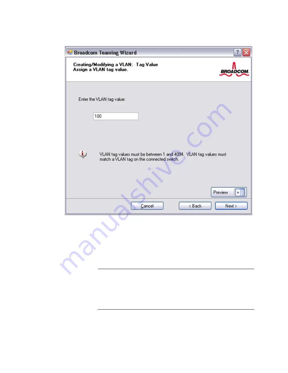
Figure 26. Creating/Modifying a VLAN: Tag Value Page

21. Select 

Yes

 to add or manage another VLAN and then click 

Next

Repeat until you do not want to add or manage any additional VLANs. 

The Creating/Modifying a VLAN: Additional VLANs Page is displayed. 
See Figure 27 on page 61.

Note

You can define up to 64 VLANs per team (63 VLANs that are tagged 
and 1 VLAN that is not tagged). Adding several VLANs may slow the 
reaction time of the Windows interface due to memory and 
processor time usage for each VLAN. The degree to which Windows 
performance suffers depends on the system configuration. 

Summary of Contents for Broadcom Advanced Control Suite 3

Page 1: ...613 001247 Rev A Broadcom Advanced Control Suite 3 User s Guide...

Page 2: ...rks or registered trademarks of their respective owners Allied Telesis Inc reserves the right to make changes in specifications and other information contained in this document without prior written n...

Page 3: ...17 Setting User Interface Appearance 17 Viewing Vital Signs 17 Viewing Driver Information 20 Displaying Resource Information 21 Testing the Network 24 Running Diagnostic Tests 25 Analyzing Cables 28 S...

Page 4: ...Contents 4...

Page 5: ...ber Page 53 Figure 20 Creating Modifying a Team Configuring LiveLink Page 54 Figure 21 Creating Modifying a Team Configuring LiveLink Page continued 1 55 Figure 22 Creating Modifying a Team Configurin...

Page 6: ...Figures 6...

Page 7: ...s well as to display and modify property values and display traffic statistics for each adapter The Broadcom Advanced Server Program BASP which runs within Broadcom Advanced Control Suite 3 is used to...

Page 8: ...the safety symbols defined in Table 1 Table 1 Safety Symbols Symbol Meaning Description Caution Performing or omitting a specific action may result in equipment damage or loss of data Warning Perform...

Page 9: ...based Guides The installation and user guides for all Allied Telesis products are available in portable document format PDF on our web site at www alliedtelesis com support software You can view the d...

Page 10: ...turned to the sender at the sender s expense For instructions on how to obtain an RMA number go to the Support section on our web site at www alliedtelesis com support rma aspx For Sales or Corporate...

Page 11: ...Framework versions for BACS3 In addition this chapter describes how to set the BACs software This chapter contains the following sections Starting Broadcom Advanced Control Suite 3 on page 12 Using B...

Page 12: ...le KB936707 To improve the startup time of BACS 3 apply NET Framework 2 0 SP1 or the appropriate version for your OS as shown in the Recommended column of Table 1 and reboot your system Note For optim...

Page 13: ...0 SP1 Download Vista SP1 from Microsoft which includes NET 2 0 SP1 Windows Server 2008 NET 2 0 Included in NET 2 0 SP1 which is included during OS installation NET 2 0 SP1 Included in OS package Tabl...

Page 14: ...gement button to manage the connected devices see Displaying Device Management Information next Or click the Team Management button to create and manage teams see Team Management on page 16 Displaying...

Page 15: ...pane click By Connection The By Connection Page is displayed See Figure 2 on page 15 The Connection View lists the server and client devices in a parent child hierarchy which makes it easier to see th...

Page 16: ...disabled Team Management The Team Management pane displays how network adapters have been grouped together to function as a team or a virtual LAN VLAN The pane separates the adapters that have been gr...

Page 17: ...Tools menu select Options 2 In the Options window select Appearance 3 Choose the appearance settings Click Apply to set changes Click OK to set changes and close the Options window To reset the inter...

Page 18: ...adapters made by other vendors Note Some information may not be available for all Allied Telesis or Broadcom based network adapters Figure 4 Device Management By Type Page MAC Address A physical MAC m...

Page 19: ...breaking a large data packet into a series of smaller packets with headers appended to them CO Checksum Offload CO allows the TCP IP UDP checksums for send and receive traffic to be calculated by the...

Page 20: ...the Information tab is not visible then from the Context View tab on the right side of the window select Information and then select Driver Figure 5 Driver Information Page Driver Status Indicates the...

Page 21: ...tab The Resources Page is displayed See Figure 6 on page 21 If the Information tab is not visible then from the View menu select Navigate Device Management and then Information If the Resources sectio...

Page 22: ...s installed Device No Indicates the number assigned to the adapter by the operating system Function No Indicates the port number of the adapter For a single port adapter the function number is 0 For a...

Page 23: ...the Hardware section within the Information tab is not visible then from the Context View tab on the right side of the window select Information and Hardware Note Some information may not be available...

Page 24: ...ress Note The network test option is not available on adapters that are grouped into a team For information about teaming see Chapter 2 Configuring Teaming on page 43 To run the network test do the fo...

Page 25: ...fails in the Status field for each test increments every time the tests are performed For example if a test is performed four times and there are no fails the value in the Status field for that test i...

Page 26: ...played in the Status field for each test To run the diagnostic tests continuously do the following 1 Click the name of the adapter to test in the Device Management pane 2 Click the Diagnostics tab If...

Page 27: ...on the wire and to configure network speeds such as 1000 Mbit s EEPROM This test verifies the content of the electrically erasable programmable read only memory EEPROM by reading a portion of the EEPR...

Page 28: ...e analysis test can only run for gigabit link speed connections and when there is no connection Note This option is not available for all Allied Telesis fiber network adapters To run a cable analysis...

Page 29: ...ser s Guide 29 6 In the error message window that warns of the network connection being temporarily interrupted click Yes Figure 10 Cable Analysis Page Distance The valid cable length in meters except...

Page 30: ...are several factors that could affect the test results Link partner Various switch and hub manufacturers implement different PHYs Some PHYs are not IEEE compliant Cable quality Category 3 4 5 and 6 m...

Page 31: ...n select the property you want to set If the Advanced section is not available then from the Context View tab on the right side of the window select Configurations and then select Advanced The Advance...

Page 32: ...ic diversely to ensure required levels or reliability and latency according to the type of traffic This property is disabled by default Unless the network infrastructure supports QoS do not enable thi...

Page 33: ...one of the following Rx Enabled Enables receive TCP IP UDP checksum offload Tx Enabled Enables transmit TCP IP UDP checksum offload Tx Rx Enabled default Enables transmit and receive TCP IP UDP checks...

Page 34: ...ect one of the following Both Disabled LSO Jumbo frames are both disabled LSO Enabled Jumbo Off default LSO enabled and jumbo frames disabled LSO Off Jumbo 3000 Frame size of 3000 bytes and LSO off LS...

Page 35: ...00 Mbit s and the mode to Full Duplex 100 Mb Half Sets the speed at 100 Mbit s and the mode to Half Duplex 1 Gb Full Auto Sets the speed to Auto Negotiate at 1000 Mb Full Duplex mode only Auto default...

Page 36: ...th its link partner but if the attached link partner is forced at 1 Gbit s it reverts to this mode Hardware Default Sets the speed to negotiate according to the setting specified by the manufacturer S...

Page 37: ...at a time Interrupt Moderation Enables adaptive interrupt coalescing which limits the rate of interrupt to the CPU during packet transmission and packet reception The disabled option allows one interr...

Page 38: ...he right side of the window select Statistics and then select the name of the missing section Click Refresh to get the most recent values for each statistic Click Reset to change all values to zero No...

Page 39: ...sfully transmitted Multicast Frames Tx A count of frames that were successfully transmitted as indicated by the status value Transmit OK to a group destination address other than a broadcast address B...

Page 40: ...eive OK status Frames Rx with CRC Error The number of frames received with CRC errors IEEE 802 3 Statistics This section describes the parameters in the IEEE 802 3 Statistics portion of the General St...

Page 41: ...rs This information is only available for Broadcom NetXtreme II adapters Frames size less than 64 byte with bad FCS The number of frames with a size less than 64 bytes with bad FCS MAC Rx w Pause Comm...

Page 42: ...Chapter 1 Starting and Using BACS 3 42...

Page 43: ...g Wizard or the Expert Mode Both methods are described in this chapter This chapter contains the following sections Defining Team Types on page 45 Using the Broadcom Teaming Wizard on page 47 Using th...

Page 44: ...ps until a threshold is met This is normal behavior Note Wake on LAN WOL is a feature that allows a system to be awakened from a sleep state by the arrival of a specific packet over the Ethernet inter...

Page 45: ...rmined by the BASP driver The link partner of the team determines the load balancing scheme for inbound packets In this mode at least one of the link partners must be in active mode Generic Trunking F...

Page 46: ...disconnected the standby member takes over the handling of the network activities In Auto Fallback Disable mode if a load balance member returns on line the team continues using the standby member ra...

Page 47: ...create a new team select Create a Team from the Team menu or right click one of the devices in the Unassigned Adapters section and select Create a Team See Figure 13 on page 47 This option is not avai...

Page 48: ...work without the wizard click Expert Mode If you want to always use Expert Mode to create a team select Default to Expert Mode on next start See Using the Expert Mode on page 65 5 To continue using th...

Page 49: ...If you want to review or change any of your settings click Back Click Cancel to discard your settings and exit the wizard The Creating Modifying a Team Team Name Page is displayed See Figure 16 on pa...

Page 50: ...e If the team type is an SLB type team click Next If the team type is not an SLB type team then a dialog box appears 8 Verify that the network switch connected to the team members is configured correc...

Page 51: ...e adapter and then clicking Remove Click Next The Creating Modifying a Team Assigning Team Members Page is displayed See Figure 18 on page 52 Note There must be at least one Broadcom network adapter a...

Page 52: ...only driver enabled network adapters are added as members to a team Figure 18 Creating Modifying a Team Assigning Team Members Page 10 If you want to designate one of the adapters as a standby member...

Page 53: ...Standby Member Page is displayed See Figure 19 Figure 19 Creating Modifying a Team Designating a Standby Member Page 12 If you want to configure LiveLink select Yes otherwise select No then click Next...

Page 54: ...efore a failover is triggered 14 Set the Probe VLAN ID to allow for connectivity with probe targets residing on a tagged VLAN The number set must match the VLAN ID of the probe targets as well as the...

Page 55: ...e continued 2 is displayed See Figure 22 on page 56 Note Only the first probe target is required You can specify up to three additional probe targets to serve as backups by assigning IP addresses to t...

Page 56: ...s of an existing VLAN select Edit VLAN then click Next The Creating Modifying a VLAN Configure VLAN Support Page is supported See Figure 23 on page 57 If you do not want to create or edit a VLAN selec...

Page 57: ...ted when all team members are Broadcom adapters Figure 23 Creating Modifying a VLAN Configure VLAN Support Page 18 Type the VLAN name and then click Next Note The team name cannot exceed 39 characters...

Page 58: ...N Naming Page 19 To tag the VLAN select Tagged and then click Next Otherwise click Untagged click Next and continue with the wizard to add additional VLANs see step 21 of this procedure The Creating M...

Page 59: ...User s Guide 59 Figure 25 Creating Modifying a VLAN Tagging Page 20 Type the VLAN tag value and then click Next The value must be between 1 and 4094 The Creating Modifying a VLAN Tag Value Page is di...

Page 60: ...l VLANs The Creating Modifying a VLAN Additional VLANs Page is displayed See Figure 27 on page 61 Note You can define up to 64 VLANs per team 63 VLANs that are tagged and 1 VLAN that is not tagged Add...

Page 61: ...al VLANs Page 22 To apply and commit the changes to the team select Commit changes to system and Exit the wizard To apply your changes but continue using the wizard select Save changes and continue to...

Page 62: ...Chapter 2 Configuring Teaming 62 Figure 28 Congratulations Page...

Page 63: ...will look like before committing any changes Figure 29 Broadcom Teaming Wizard Commit Changes Page 23 Click the team name in the Team Management pane to view the team s properties in the Information t...

Page 64: ...Chapter 2 Configuring Teaming 64 Figure 30 Team Properties Page...

Page 65: ...using the Wizard Mode see Using the Broadcom Teaming Wizard on page 47 Creating a Team To create a team in the Expert mode do the following Note Enabling Dynamic Host Configuration Protocol DHCP is n...

Page 66: ...ns which means all adapters are already assigned to teams Figure 31 Creating A Team Path 4 Click Expert Mode The Manage Teams Page Create Team Tab is displayed See Figure 32 on page 66 If you want to...

Page 67: ...Manage Members at the top of the window The Manage Load Balance Members Window is displayed See Figure 33 Figure 33 Manage Load Balance Members Window 9 Assign any available adapter or adapters to th...

Page 68: ...refore it is recommended that only driver enabled network adapters be added as members to a team 11 Click OK to accept your changes to the team members 12 Click Create to save the team information 13...

Page 69: ...ng and Failover and SLB Auto Fallback Disable types of teams Note For an SLB Auto Fallback Disable team to restore traffic to the load balance members from the standby member click the Fallback button...

Page 70: ...Management button at the bottom of the BACS 3 window Or from the View menu select Navigate and then select Team Management 2 Select one of the teams listed 3 From the Team menu click Edit Team or rig...

Page 71: ...Make the desired changes and then click Update The changes have not yet been applied click the Preview tab to view the updated team structure before proceeding to the next step to apply the changes 7...

Page 72: ...rs If you try to create a VLAN with a non Broadcom adapter an error message is displayed To configure a team with a VLAN do the following 1 Click the Team Management button at the bottom of the BACS 3...

Page 73: ...Tests This section discusses how to display VLAN Properties and statistics as well as how to delete VLANs To display VLAN properties and statistics and to run VLAN tests do the following 1 Click the...

Page 74: ...to Fallback Disable type of teaming The purpose of LiveLink is to detect link loss beyond the switch and to route traffic only through team members that have a live link Read the following notes befor...

Page 75: ...3 From the Teams menu select Edit Team 4 Click Expert Mode To configure LiveLink using the Teaming Wizard see Using the Broadcom Teaming Wizard on page 47 5 In the Manage Teams window click the Edit...

Page 76: ...eams Tab 7 Set the Probe VLAN ID to correspond with the VLAN where the probe target s resides This step applies the appropriate VLAN tag to the link packet based on the shared configuration of the att...

Page 77: ...e targets to serve as backups by assigning IP addresses to the other probe targets 9 Select one of the listed team members and type the member IP address Note All of the member IP addresses must be in...

Page 78: ...ns information about both the adapter and the team configuration To restore a configuration do the following 1 From the File menu select Team Restore 2 Click the name of the file to be restored and th...

Page 79: ...Team Management pane then click the Statistics tab Here are some guidelines for displaying statistics If the Statistics tab is not visible then from the View menu select Navigate Team Management and t...

Page 80: ...Chapter 2 Configuring Teaming 80 Figure 38 General Page...

Reviews: