background image

5

100Base-FX Fiber Optic Ports  ..........................................................................................................................................................................22

Type of Connector........................................................................................................................................................................................22
Speed ................................................................................................................................................................................................................22
Duplex Mode..................................................................................................................................................................................................22
Maximum Distance......................................................................................................................................................................................22
Type of Cable .................................................................................................................................................................................................22

Power Over Ethernet ...........................................................................................................................................................................................23

AT-8524POE’s Implementation of PoE .................................................................................................................................................24
Power Budgeting..........................................................................................................................................................................................24

GBIC and SFP Expansion Slots  .........................................................................................................................................................................26
Module Expansion Slots  ....................................................................................................................................................................................27
Twisted Pair Port LEDs and the LED Mode Select Button ......................................................................................................................28
Fiber Optic Port LEDs ..........................................................................................................................................................................................32
GBIC and SFP Expansion Slot LEDs  ................................................................................................................................................................33
System LEDs ...........................................................................................................................................................................................................34
RS-232 Terminal Port  ..........................................................................................................................................................................................35
RPS Connector .......................................................................................................................................................................................................36
AC Power Connector ...........................................................................................................................................................................................37
DC Power Connector  ..........................................................................................................................................................................................38
A Few Basics about Ethernet Switching .......................................................................................................................................................39

MAC Address Table......................................................................................................................................................................................39
Duplex Mode..................................................................................................................................................................................................40
Store and Forward........................................................................................................................................................................................41
Backpressure and Flow Control ..............................................................................................................................................................41

Network Topologies ............................................................................................................................................................................................42

Power Workgroup Topology....................................................................................................................................................................42
Collapsed Backbone Topology................................................................................................................................................................43
Mixed Topology ............................................................................................................................................................................................44

Chapter 2

Installation 

............................................................................................................................................................................................................45

Reviewing Safety Precautions  .........................................................................................................................................................................46
Selecting a Site for the Switch .........................................................................................................................................................................47
Planning the Installation  ...................................................................................................................................................................................48
Unpacking the Switch  ........................................................................................................................................................................................50
Installing the Switch in a Rack .........................................................................................................................................................................51
Installing an Optional Expansion or Stacking Module  ...........................................................................................................................53

For the AT-8516F/SC, AT-8524M, and AT-8524POE .........................................................................................................................53

Installing an Optional GBIC Module ..............................................................................................................................................................56

For the AT-8550GB.......................................................................................................................................................................................56

Installing an Optional SFP Module  ................................................................................................................................................................58

For the AT-8550SP........................................................................................................................................................................................58

Cabling and Powering On the Switch  ..........................................................................................................................................................60
Wiring a DC Powered Unit  ................................................................................................................................................................................66
Starting a Local Management Session  .........................................................................................................................................................69
Warranty Registration .........................................................................................................................................................................................71

Chapter 3

Troubleshooting 

................................................................................................................................................................................................72

Appendix A

Technical Specifications 

.................................................................................................................................................................................77

Physical Specifications  .......................................................................................................................................................................................77
Environmental Specifications ..........................................................................................................................................................................78
Power Specifications ...........................................................................................................................................................................................79
Safety and Electromagnetic Emissions Certifications .............................................................................................................................80

Summary of Contents for AT-8550/SP Series

Page 1: ...AT 8500 Series Layer 2 Fast Ethernet Switches AT 8516F SC AT 8524M AT 8524POE AT 8550GB AT 8550SP Installation Guide PN 613 50484 00 Rev C ...

Page 2: ...ein are trademarks or registered trademarks of their respective owners Allied Telesyn Inc reserves the right to make changes in specifications and other information contained in this document without prior written notice The information provided herein is subject to change without notice In no event shall Allied Telesyn Inc be liable for any incidental special indirect or consequential damages wha...

Page 3: ...sicurezza nella propria lingua Viktig Tillegg C inneholder oversatt sikkerhetsinformasjon for installering av dette utstyret Når du ser åpner du til Tillegg C for å finne den oversatte sikkerhetsinformasjonen på ønsket språk Importante O Anexo C contém advertências de segurança traduzidas para instalar este equipamento Quando vir o símbolo leia a advertência de segurança traduzida no seu idioma no...

Page 4: ...formation 10 Management Software Updates 10 Chapter 1 Overview 11 Model Descriptions 12 AT 8516F SC 12 AT 8524M 13 AT 8524POE 14 AT 8550GB 15 AT 8550SP 16 Hardware Features 17 10 100Base TX Twisted Pair Ports 18 Type of Connector 18 Speed 18 Duplex Mode 18 Maximum Distance 19 Type of Cabling 19 Auto MDI MDI X 19 Port Pinouts 19 10 100 1000Base T Twisted Pair Ports 20 Type of Connector 20 Speed 20 ...

Page 5: ...ies 42 Power Workgroup Topology 42 Collapsed Backbone Topology 43 Mixed Topology 44 Chapter 2 Installation 45 Reviewing Safety Precautions 46 Selecting a Site for the Switch 47 Planning the Installation 48 Unpacking the Switch 50 Installing the Switch in a Rack 51 Installing an Optional Expansion or Stacking Module 53 For the AT 8516F SC AT 8524M and AT 8524POE 53 Installing an Optional GBIC Modul...

Page 6: ...ort 82 RJ 45 Twisted Pair Port Pinouts 83 AT 8516F SC Fiber Optic Port Specifications 86 RS 232 Terminal Port Pinouts 87 RPS Connector Port Pinouts 88 Dual SC Type Connector 91 Appendix B Translated Electrical Safety and Emission Information 92 ...

Page 7: ...w describes the features and components of the switch Chapter 2 Installation contains the installation instructions Chapter 3 Troubleshooting provides information on how to resolve problems that might occur with the switch Appendix A Technical Specifications contains the switch s technical specifications Appendix B Translated Electrical Safety and Emission Information contains translations of the ...

Page 8: ...ntions Note Notes provide additional information Caution Cautions inform you that performing or omitting a specific action may result in equipment damage or loss of data Warning Warnings inform you that performing or omitting a specific action may result in bodily injury ...

Page 9: ...b site at www alliedtelesyn com You can view the documents online or download them onto a local workstation or server Once you have installed your AT 8500 Series Switch refer to following manuals for instructions on how to manage and configure the unit The manuals are available from the Allied Telesyn web site AT S62 Management Software User s Guide PN 613 50485 00 AT S62 Command Line Interface Us...

Page 10: ... A product sent to Allied Telesyn without a RMA number will be returned to the sender at the sender s expense To obtain a RMA number contact Allied Telesyn s Technical Support at our web site www alliedtelesyn com For Sales or Corporate Information You can contact Allied Telesyn for sales or corporate information at our web site www alliedtelesyn com To find the contact information for your countr...

Page 11: ...SC 16 100Base FX ports with dual SC connectors plus two expansion slots for optional fiber optic and twisted pair port expansion modules AT 8524M 24 10 100Base TX ports plus two expansion slots for optional fiber optic and twisted pair port expansion modules AT 8524POE 24 10 100Base TX ports with Power Over Ethernet technology plus two expansion slots for optional fiber optic and twisted pair port...

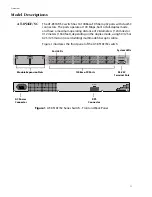
Page 12: ...6F SC switch Figure 1 AT 8516F SC Series Switch Front and Back Panel FAULT RPS MASTER PWR STATUS 18 17 D C L A D C L A D C L A D C L A D C L A D C L A D C L A D C L A D C L A D C L A D C L A D C L A D C L A D C L A D C L A D C L A LINK ACTIVITY HALF DUP COL FULL DUP L A D C PORT ACTIVITY AT 8516F SC 100Base FX Fast Ethernet Switch RS 232 TERMINAL PORT 1 TX RX 9 TX RX 2 TX RX 10 TX RX 3 TX RX 11 TX...

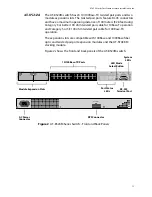
Page 13: ...compatible with 100Base and 1000Base fiber optic and twisted pair port expansion modules and the AT STACKM stacking module Figure 2 shows the front and back panels of the AT 8524M switch Figure 2 AT 8524M Series Switch Front and Back Panels 1 3 5 7 9 11 13 15 17 19 21 23 2 4 6 8 10 12 14 16 18 20 22 24 LINK MODE LINK MODE COL 100 FULL ACT FAULT RPS MASTER PWR MODE 1 3 5 7 9 11 2 4 6 8 10 12 13 15 ...

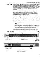
Page 14: ...eration The switch also features two expansion slots that are compatible with 100Base and 1000Base fiber optic and twisted pair port expansion modules and the AT STACKM stacking module Figure 2 shows the front and back panels of the AT 8524POE switch Figure 3 AT 8524POE Series Switch Front and Back Panels 1 3 5 7 9 11 13 15 17 19 21 23 2 4 6 8 10 12 14 16 18 20 22 24 FAULT RPS MASTER PWR MODE 1 3 ...

Page 15: ... distance of your network For a list of GBIC modules supported by the switch contact your Allied Telesyn sales representative or refer to the Allied Telesyn web site www alliedtelesyn com Note The twisted pair ports 49R and 50R change to a redundant status when GBIC modules are installed and establish links with their end nodes A link on a GBIC port always takes precedence over that of the corresp...

Page 16: ...act your Allied Telesyn sales representative or refer to the Allied Telesyn web site www alliedtelesyn com Note The twisted pair ports 49R and 50R change to a redundant status when SFP modules are installed and establish links with their end nodes A link on a SFP port always takes precedence over that of the corresponding 10 100 1000Base T twisted pair port Figure 4 shows the front and back panels...

Page 17: ...Pair Ports on page 20 100Base FX Fiber Optic Ports on page 22 Power Over Ethernet on page 23 GBIC and SFP Expansion Slots on page 26 Module Expansion Slots on page 27 Twisted Pair Port LEDs and the LED Mode Select Button on page 28 Fiber Optic Port LEDs on page 32 GBIC and SFP Expansion Slot LEDs on page 33 System LEDs on page 34 RS 232 Terminal Port on page 35 RPS Connector on page 36 AC Power Co...

Page 18: ...vate Auto Negotiation and set the speeds manually refer to the AT S62 Management Software User s Guide Duplex Mode Each twisted pair port on the switch can operate in either half or full duplex mode The twisted pair ports are IEEE 802 3u compliant and will Auto Negotiate the duplex mode setting If desired you can disable Auto Negotiation on one or all of the switch ports so that you can set the du...

Page 19: ...lves as either MDI or MDI X depending on the configuration of the port on the end node This feature allows you to use either straight through or crossover twisted pair cables to connect devices to the ports Note The auto MDI MDI X feature on a port is available only when the port is set to Auto Negotiation If you disable Auto Negotiation and set a port s speed and duplex mode manually the port def...

Page 20: ...ally through the management software Note In order for a 10 100 1000Base T port to successfully Auto Negotiate its duplex mode with an end node the end node should also be using Auto Negotiation Otherwise a duplex mode mismatch can occur A port using Auto Negotiation will default to half duplex if it detects that the end node is not using Auto Negotiation This will result in a mismatch if the end ...

Page 21: ... 100 1000Base T port is functional only when the port is set to Auto Negotiation If you disable Auto Negotiation and set the port s speed and duplex mode manually the port defaults to MDI X For instructions on configuring a port refer to the AT S62 Management Software User s Guide or the AT S62 Command Line User s Guide Port Pinouts For the pinouts of these ports when operating at 10 or 100 Mbps r...

Page 22: ... ports can operate in either half or full duplex mode You can set the duplex mode manually or allow the switch to set it automatically through Auto Negotiation Maximum Distance Each fiber optic port has a maximum operating distance of two kilometers 1 25 miles when operating in full duplex mode and 412 meters 1 360 feet when operating in half duplex mode Type of Cable The fiber optic ports can use...

Page 23: ...ver the same twisted pair cable There are several advantages that the PoE feature of the AT 8524POE switch adds to the installation and maintenance of your network First since the switch acts as the central power source for your powered devices adding a redundant power supply RPS or uninterruptible power source UPS to the switch increases the protection not just to the switch itself from possible ...

Page 24: ...rk traffic The power and the network traffic can coexist on the same strands simultaneously Powered devices that comply with the IEEE 802 3af standard typically support both methods of power delivery methods So you should not need to concern yourself about whether a powered device is compatible with the switch s power delivery method So long as a powered device is compliant with the standard it sh...

Page 25: ...nce a switch port can determine for itself whether the device connected to it is a powered device or not and if it is how much power is required there should be little need for you to configure PoE on the switch The AT S62 management software also allows you to prioritize the ports in the event there is not be enough PoE power for all the powered devices This feature can help ensure that the most ...

Page 26: ... of your network build a high speed backbone network between switches or connect additional end nodes to the network such as high speed servers Figure 6 shows an example of a fiber optic GBIC module Figure 6 GBIC Module When you install a GBIC or SFP module in Port 49 or Port 50 and the module establishes a link with its end node the corresponding twisted pair port Port 49R or 50R changes to a red...

Page 27: ...expansion slots Each slot can accommodate an expansion module You can use the slots to add 100Base and 1000Base fiber optic and twisted pair ports to the switch Note For a list of the Allied Telesyn expansion modules supported by the switches contact your Allied Telesyn sales representative or refer to our web site at www alliedtelesyn com ...

Page 28: ...on does not affect the normal operations of the switch Table 2 describes the LEDs for the 10 100Base TX twisted pair ports on the AT 8524M AT 8550GB and AT 8550SP switches Table 2 LEDs for the 10 100Base TX Twisted Pair Ports on the AT 8524M AT 8550GB and AT 8550SP Switches LED State Description LINK OFF Indicates that there is no link between the port and the end node Green Indicates a valid link...

Page 29: ...the port Flashing Green Indicates that the port is transmitting and or receiving data packets Table 3 LEDs for Ports 49R and 50R on the AT 8550GB and AT 8550SP Switches LED State Description LINK OFF Indicates that there is no link between the port and the end node Green Indicates a valid link has been established between the port and the end node Mode COL OFF Indicates that no data collisions are...

Page 30: ...or the 10 100Base TX Twisted Pair Ports on the AT 8524POE Switch LED State Description L A OFF Indicates that the port has not established a link with its end node Steady Green Indicates the port has established a valid 100 Mbps link with its end node Flashing Green Indicates the port is receiving or transmitting packets at 100 Mbps Steady Amber Indicates the port has established a valid 10 Mbps l...

Page 31: ...ected to the port is not a powered device and does not require PoE Green Indicates that the end node is a powered device and that the port is providing power to it Steady Amber Indicates that the port experienced a problem providing PoE to the end node For further information refer to Chapter 3 Troubleshooting on page 72 Flashing Amber Indicates that the port is connected to a powered device but t...

Page 32: ...ic Ports on the AT 8516F SC Switch LED State Description L A OFF Indicates no link has been established between the port and the end node Green Indicates a valid link exists between the port and the end node Flashing Green Indicates that the port is transmitting and or receiving data packets D C Green Indicates that the port is operating in full duplex mode Amber Indicates that the port is operati...

Page 33: ...escription LINK OFF Indicates that there is no link between the port and the end node Solid Green Indicates a valid link has been established between the port and the end node Mode COL OFF Indicates that no data collisions are occurring on the port Flashing Green Indicates that data collisions are occurring on the port Mode SPD Solid Green Indicates that the port is operating at 1000 Mbps Mode FDX...

Page 34: ...on the switch or management software may have experienced a malfunction Refer to Troubleshooting on page 72 for instructions on how to troubleshoot a problem MASTER or MSTR Green Indicates that the switch is functioning as the master switch of an enhanced stack OFF Indicates that the switch is a slave switch or is not a member of a stack RPS Green Indicates that an optional redundant power supply ...

Page 35: ...t Note You are not required to manage an AT 8500 Series switch If the default switch settings are adequate for your network you can use the unit as an unmanaged switch For the default settings refer to the AT S62 Management Software User s Guide The RS 232 terminal port has a DB 9 female connector and uses a straight through RS 232 cable included with the switch The default settings for the RS 232...

Page 36: ...s three empty slots for additional power modules Each power module can support one switch making the AT RPS3004 unit capable of supporting up to four switches simultaneously Note The AT RPS3004 unit is compatible with all AT 8500 Series switches except for the AT 8524POE switch The latter uses the AT RPS3104 unit which was not available at the time of publication of this document Do not use the AT...

Page 37: ... AC Power Connector The switch has a single AC power supply socket on the back panel which has autoswitch AC inputs To power the switch on or off you connect or disconnect the power cord Refer to Technical Specifications on page 77 for the input voltage range ...

Page 38: ...ith a DC terminal block on the back panel instead of an AC socket for those network installations that require DC equipment Refer to Technical Specifications on page 77 for the input voltage range and Wiring a DC Powered Unit on page 66 for instructions on how to wire a DC powered unit ...

Page 39: ...at are connected to the switch s ports and the port number where each address was learned When the switch receives a packet it also examines the destination address and by referring to its MAC address table determines the port on which the destination end node is connected It then forwards the packet to the appropriate port and on to the end node This increases network bandwidth by limiting each p...

Page 40: ...ge the setting for a port on the switch should you replace an end node with an end node that has a different duplex mode capability With Auto Negotiation the switch automatically resets the port to a new duplex mode setting If desired you can disable Auto Negotiation on the switch ports so that you can set the duplex mode manually through the switch s management software Note In order for a switch...

Page 41: ...depending on the speed and duplex mode of the end node and switch port A twisted pair port operating at 100 Mbps port and half duplex mode stops an end node from transmitting data by forcing a collision A collision on an Ethernet network occurs when two end nodes attempt to transmit data using the same data link at the same time A collision causes end nodes to stop sending data When the switch nee...

Page 42: ...rred to as a power workgroup topology Each workstation or end node is connected directly to a port on an AT 8524M Fast Ethernet Switch This provides each end node with a dedicated data link to the switch for best performance and reliability The devices can operate at either 10 Mbps or 100 Mbps Figure 8 Power Workgroup Topology MODE STATUS AT 8524M Fast Ethernet Switch Legend 10 Mbps 100 Mbps AT 85...

Page 43: ...cting as a bridge between the different workgroups The switch transfers an Ethernet frame from hub to hub only when the destination end node for the frame is on a different hub than the end node that originated the frame This reduces the amount of unnecessary data traffic in each workgroup freeing up bandwidth and improving network performance Figure 9 Collapsed Backbone Topology MODE STATUS AT 85...

Page 44: ...ork of three AT 8524M Fast Ethernet switches The workstations and servers on the network are connected either directly to a switch or indirectly through an Ethernet hub The switches themselves are connected together through 1000Base fiber optic ports on AT A45 SC expansion modules creating a high speed backbone Figure 10 Mixed Topology AT 8524M AT 8524M 1 5 4 3 2 6 7 8 Legend 10 Mbps 100 Mbps 1 5 ...

Page 45: ...e 51 Installing an Optional Expansion or Stacking Module on page 53 Installing an Optional GBIC Module on page 56 Installing an Optional SFP Module on page 58 Cabling and Powering On the Switch on page 60 Wiring a DC Powered Unit on page 66 Starting a Local Management Session on page 69 Warranty Registration on page 71 Note For installation instructions for the optional AT RPS3004 Redundant Power ...

Page 46: ...Lightning Danger Do not work on this equipment or cables during periods of lightning activity 9 Warning Power cord is used as a disconnection device To de energize equipment disconnect the power cord 10 Warning Electrical Type Class 1 Equipment This equipment must be earthed The power plug must be connected to a properly wired earth ground socket outlet An improperly wired socket outlet could plac...

Page 47: ...level and secure The power outlet for the switch should be located near the unit and should be easily accessible The site should provide for easy access to the ports on the front of the switch This will make it easy for you to connect and disconnect cables as well as to view the switch s LEDs To allow proper cooling of the switch air flow around the unit and through its vents on the side and rear ...

Page 48: ... manually using the AT S62 management software A port where Auto Negotiation has been disabled defaults to MDI X Disabling Auto Negotiation may require that you manually configure a port s MDI MDI X setting or use a crossover cable Table 8 Twisted Pair Cabling and Distances Model Speed Type of Cable Maximum Operating Distance AT 8524M AT 8524POE AT 8550GB AT 8550SP 10 Mbps Category 3 or better 100...

Page 49: ...contains the cabling specifications for the fiber optic ports on an AT 8516F SC switch Note For cabling specifications for an optional GBIC module SFP module expansion module or stacking module refer to the installation guide included with the option Table 9 Fiber Optic Cabling and Distance Model Speed Type of Cable Maximum Operating Distance AT 8516F SC 100 Mbps 50 125 or 62 5 125 micron core cla...

Page 50: ...to Allied Telesyn 2 Place the switch on a level secure surface 3 Make sure the following hardware components are included in your switch package If any item is missing or damaged contact your Allied Telesyn sales representative for assistance One AT 8500 Series Fast Ethernet Switch Two mounting brackets Eight flathead Phillips screws AC power cord AC switches only Americas EC Australia and UK only...

Page 51: ...he front of the rack Method A Flush with front of rack Method B 4 5cm 1 75 in Method C 18 4 cm 7 25 in Method D 21 6 cm 8 5 in Figure 11 Rackmount Bracket Positions Note The AT 8524POE switch supports only Methods A and B 17 19 21 23 18 20 22 24 COL 100 FULL ACT FAULT RPS MASTER PWR MODE STATUS AT 8524M Fast Ethernet Switch 17 19 21 23 18 20 22 24 COL 100 FULL ACT FAULT RPS MASTER PWR MODE STATUS ...

Page 52: ...move the snap on plastic feet from the bottom of the switch as shown in Figure 12 Figure 12 Removing the Feet 3 Turn the switch over 4 Attach a rackmounting bracket to one side of the switch using four of the screws that came with theswitch You can install the brackets in one of four ways as shown in Figure 11 5 Install the second rackmounting bracket on the other side of the switch using the four...

Page 53: ...l if you need to return the module to Allied Telesyn Warning An expansion or stacking module can be damaged by static electricity Be sure to observe all standard electrostatic discharge ESD precautions such as wearing an antistatic wrist strap to avoid damaging the module 2 Refer to the module s installation guide for a list of the items included with the option If any item is missing or damaged c...

Page 54: ...he faceplate in a safe area in case you need to reinstall it The faceplate keeps any dust from getting into the switch and maintains proper airflow if the slot remains empty 6 Carefully slide the module into the slot until the module faceplate makes contact with the switch as shown in Figure 14 Avoid touching the module components Figure 14 Installing a Module 10 100 1000BASE T AT A46 10 100 FULL ...

Page 55: ...d on the module faceplate as shown in Figure 15 Figure 15 Tightening the Module Installation Screws Caution Always use the installation screws to secure the module to the switch Leaving a module partially seated may cause the system to halt and subsequently crash 10 100 1000BASE T AT A46 10 100 FULL DUPLEX ACTIVITY LINK 1000 ...

Page 56: ...ic discharge ESD precautions such as wearing an antistatic wrist strap to avoid damaging the module 2 Check that the GBIC package includes all the items listed below If any item is missing or damaged contact your Allied Telesyn sales representative for assistance One GBIC module Installation Guide Warranty card Note For fiber optic cabling specifications refer to the GBIC Installation Guide provid...

Page 57: ... Note Unnecessary removal and insertion of a GBIC can lead to premature failure 4 SlidetheGBICmodule withthelabelsideup intoanexpansionslot on the switch as shown in Figure 17 The GBIC can be installed in either slot The GBIC module is completely seated in the slot when it clicks into place Figure 17 Installing a GBIC Module 5 If you purchased two GBIC modules for the switch repeat this procedure ...

Page 58: ...static discharge ESD precautions such as wearing an antistatic wrist strap to avoid damaging the module 2 Check that the SFP module comes with the items listed below If any item is missing or damaged contact your Allied Telesyn sales representative for assistance One SFP module Installation Guide Warranty card Note For fiber optic cabling specifications refer to the SFP Installation Guide provided...

Page 59: ...ule can lead to premature failure 4 Slide the SFP module with the label side up into an SFP expansion slot on the switch The SFP module can be installed in either slot The SFP module is completely seated in the slot when it clicks into place Note Do not remove the dust cover from the SFP module until you are ready to install the fiber optic cable When you do remove the dust cover keep it for futur...

Page 60: ...u can use either a straight through orcrossover twisted pair cable to connect any type of network device to a port on the switch If you disable Auto Negotiation on a port the auto MDI MDI X feature is disabled and the port defaults to MDI X For instructions on how to configure a port refer to the AT S62 Management Software User s Guide or AT S62 Command Line User s Guide If your network topology w...

Page 61: ...ommand Line User s Guide When connecting a device to a port on an AT 8524POE switch the port automatically determines whether the node is a powered device and if it is the amount of wattage required by the device up to a maximum of 15 4 W If the node is not a powered device the port automatically disables the PoE feature 2 If your switch has fiber optic ports remove the dust covers from the ports ...

Page 62: ... connectors as shown in Figure 21 Each connects to a separate fiber strand One is for receiving packets and the other is for transmitting packets When you connect a fiber optic cable to a dual SC port be sure that the receiver fiber connector is connected to the transmitter connector on the remote end node and the transmitter fiber connector is connected to the receiver connector on the remote nod...

Page 63: ...ontain a loop where two or more network devices can communicate with each other over more than one data path do not connect the network cables forming the loop until after you have activated a spanning tree protocol on the switch Data loops can adversely affect network performance For information on spanning tree refer to the AT S62 Management Software User s Guide or AT S62 Command Line User s Gu...

Page 64: ...gure 22 and plugging the other end into a wall outlet Warning The power cord is used as a disconnection device To de energize equipment disconnect the power cord 10 Figure 22 Connecting the AC Power Cord When power is applied the switch begins to load the AT S62 software The loading process takes approximately 20 to 30 seconds to complete ...

Page 65: ...unit is compatible with all AT 8500 Series switches except for the AT 8524POE switch The latter uses the AT RPS3104 unit which was not available at the time of publication of this document Do not use the AT RPS3004 unit with an AT 8524POE switch The switch is now ready for network operations No further installation steps are required if you do not intend to change the default operating parameter s...

Page 66: ...ting the wiring to the breaker 16 Note A tray cable is required to connect the power source if the unit is powered by centralized DC power The tray cable must be UL listed Type TC tray cable and rated at 600 V and 90 degree C with three conductors minimum 14 AWG 2 On the rear side of the chassis is a DC terminal block Starting from the left side of the terminal block identify the positive frame gr...

Page 67: ...ewdriver as shown in Figure 26 Warning When installing this equipment always ensure that the frame ground connection is installed first and disconnected last 18 Figure 26 Connecting the Stripped Wire 5 Connect the positive feed wire to the terminal block marked 6 Connect the negative feed wire to the terminal block marked Warning Check to see if there are any exposed copper strands coming from the...

Page 68: ...e circuit breaker is in the Off position 9 Connect the DC wires to the circuit breaker Refer Power Specifications on page 79 for power requirements 10 Power on the circuit breaker 11 Verify that the PWR LED on the front of the unit is green If the PWR LED is OFF refer to Troubleshooting on page 72 The switch runs a series of self diagnostic tests which take a few seconds to perform After the self ...

Page 69: ...ch and then using the enhanced stacking feature to access the new switch For instructions refer to the AT S62 Management Software User s Guide or the AT S62 Command Line User s Guide To start a local management session perform the following procedure 1 Connect one end of the RS 232 straight through management cable included with the AT 8500 Series switch to the RS 232 terminal port on the switch S...

Page 70: ...press Return to start the switch 4 Press the Return key You are prompted for a user name and password 5 To view and configure all of the switch s operating parameters enter the login name manager The default password for manager access is friend To only view the parameter settings enter the login name operator The default password for operator access is operator The user names and passwords are ca...

Page 71: ...AT 8500 Series Fast Ethernet Switch Installation Guide 71 Warranty Registration When you have finished installing the switch fill out the enclosed warranty card and mail it to Allied Telesyn ...

Page 72: ...10 for contact information Check the PWR LED on the front of the switch If the LED is OFF indicating that the unit is not receiving power do the following Make sure that the power cord is securely connected to the power source and to the AC connector on the back panel of the switch Verify that the power outlet has power by connecting another device to it Try connecting the unit to another power so...

Page 73: ...efaults to MDI X For port pinouts refertoRJ 45TwistedPairPort Pinouts on page 83 Make sure that the operating parameters of the port on the switch are compatible with the end node to which the port is connected This may require that you use the switch s management software For instructions refer to the AT S62 Management Software User s Guide or the AT S62 Command Line User s Guide For fiber optic ...

Page 74: ...tic port with a maximum distance of 40 kilometers 24 8 miles and an operating wavelength of 1550 nm to a remote fiber optic port with an maximum distance of only 2 kilometers 1 24 miles and a wavelength of 1310 nm Check to be sure that the fiber optic ports on the switch and on the end node are operating at the same speed and duplex mode AT 8550GB and AT 8550SP switches only Verify that the GBIC m...

Page 75: ...ment software is saving a change to its configuration If it remains on for an extended period do the following Try resetting the switch by disconnecting and reconnecting the AC power cord If the switch is a DC model reset the unit by powering off and the powering on the DC circuit If the FAULT LED remains ON try downloading a new version of the switch s management software through the RS 232 termi...

Page 76: ... operating parameters on the terminal or the terminal emulation program if you are using a personal computer have been set correctly The default settings for the RS 232 terminal port can be found in Starting a Local Management Session on page 69 ...

Page 77: ...50GB and AT 8550SP 4 4 cm x 44 0 cm x 25 5 cm Dimensions 1 75 in x 17 3 in x 10 0 in H x W x D AT 8524POE Dimensions 4 4 cm x 43 8 cm x 40 6 cm 1 75 in x 17 25 in x 16 0 in H x W x D Weight AT 8516F SC 3 4 kg 7 4 lb AT 8524M 3 2 kg 7 1 lb AT 8524POE 6 0 kg 13 3 lb AT 8550GB 3 6 kg 7 9 lb AT 8550SP 3 5 kg 7 7 lb Recommended Minimum Ventilation on All Sides 10 cm 4 0 in ...

Page 78: ...ing Temperature 0 C to 40 C 32 F to 104 F Storage Temperature 25 C to 70 C 13 F to 158 F Operating Humidity 5 to 90 non condensing Storage Humidity 5 to 95 non condensing Maximum Operating Altitude 4 000 m 13 000 ft Maximum Non operating Altitude 4 000 m 13 000 ft ...

Page 79: ...Power Specifications Input Voltage All models excluding AT 8524POE AC 100 240 VAC 2A maximum 50 60 Hz DC 36 60 VDC 4A maximum AT 8524POE AC 100 240 VAC 6A maximum 50 60 Hz Maximum Power Consumption All models excluding AT 8524POE 74 watts AT 8524POE 497 watts ...

Page 80: ...afety and Electromagnetic Emissions Certifications EMI FCC Class A EN55022 Class A VCCI Class A C TICK EN61000 3 2 EN61000 3 3 Immunity EN55024 Safety UL 60950 UL cUL EN60950 TUV Quality and Reliability MTBF 90 000 hrs MTTR 1 2 hr ...

Page 81: ... IEEE 802 3x Flow Control IEEE 802 3ad Link Aggregation IEEE 802 1x Port Based Network Access Control IEEE 802 1Q Port based and tagged VLANs IEEE 802 1p Class of Service IEEE 802 1d Spanning Tree Protocol IEEE 802 1w Rapid Spanning Tree Protocol IEEE 802 1s Multiple Spanning Tree Protocol RFC 1112 IGMP Snooping Version 1 0 RFC 2236 IGMP Snooping Version 2 0 ...

Page 82: ...cations 82 SNMP Support RFC 1213 MIB II RFC 1215 TRAP MIB RFC 1493 Bridge MIB RFC 1643 Ethernet MIB RFC 2863 Interface Group MIB Allied Telesyn MIBs for the AT 8500 Series switch atistackswitch mib and atistackinfo mib ...

Page 83: ...J 45 port Figure 28 RJ 45 Port Pin Layout Table 10 lists the RJ 45 pin signals for the 10 100Base TX ports on the AT 8524M AT 8550GB and AT 8550SP switches Table 10 10 100Base TX Port MDI MDI X Pin Signals Pin MDI Signal MDI X Signal 1 TX RX 2 TX RX 3 RX TX 4 Unused Unused 5 Unused Unused 6 RX TX 7 Unused Unused 8 Unused Unused Pin 1 ...

Page 84: ... depending on the requirements of the powered device connected to a port RX and Vport 1 2 TX and Vport 1 RX and Vport 1 3 RX and Vport 22 2 Vport 2 can be positive or negative depending on the requirements of the powered device connected to a port If Vport 1 is positive then Vport 2 will be negative If Vport 1 is negative then Vport 2 will be positive TX and Vport 2 4 Unused Unused 5 Unused Unused...

Page 85: ...T ports on the AT 8550GB switch when the ports are operating at 1000 Mbps Table 12 MDI and MDI X Pin Signals 1000Base T MDI Configuration MDI X Configuration Pinout Pair Pinout Pair 1 Pair 1 1 Pair 2 2 Pair 1 2 Pair 2 3 Pair 2 3 Pair 1 4 Pair 3 4 Pair 4 5 Pair 3 5 Pair 4 6 Pair 2 6 Pair 1 7 Pair 4 7 Pair 3 8 Pair 4 8 Pair 3 ...

Page 86: ...Dual SC Connector Type of Cabling 50 125 micron or 62 5 125 micron core cladding multimode fiber optic cabling Operating Wavelength 1310 nm Transmitter Output Power 50 125 micron cabling Minimum 22 5 dBm average Maximum 14 dBm average 62 5 125 micron cabling Minimum 19 dBm average Maximum 14 dBm average Receiver Sensitivity Minimum 31 dBm average Maximum 14 dBm average ...

Page 87: ...Port Pinouts Table 13 lists the pin signals on the RS 232 terminal port Table 13 RS 232 Terminal Port Pin Signals Pin Signal 1 Data Carrier Detect 2 Transmit Data 3 Receive Data 4 Data Set Ready 5 Ground 6 Data Terminal Ready 7 Clear to Send 8 Request to Send 9 Ring Indicator ...

Page 88: ...pin Molex Connector Pin Layout Table 14 lists the 16 pin RPS connector pins and definitions Table 14 Pin Definitions of the 16 pin RPS Connector Pin Definition 1 5V DC 2 Remote Sense RS 3 3 V DC 3 RS 3 3 V DC 4 RS 2 5V DC 5 Redundant Power Supply RPS present 6 2 5V DC Return 7 3 3V DC Return 8 3 3V DC 9 5V DC Return 10 2 5V DC 11 2 5 DC Return 12 2 5V DC 13 2 5V DC Return 14 2 5V DC 15 3 3V DC 16 ...

Page 89: ...ble 15 lists the RPS connector pins and definitions 16 3 3V DC Return Table 15 Pin Definitions for the RPS Connector on the AT 8524POE Switch Pin Definition A1 48V Return A2 Return 1 48V 2 48V RS 3 Redundant Power Supply RPS present 4 12V RS 5 12V RS 6 12V 7 3 3V 8 48V 9 48V 10 48V RS 11 RPS GOOD Table 14 Pin Definitions of the 16 pin RPS Connector Continued Pin Definition A1 A2 1 7 15 8 ...

Page 90: ...Technical Specifications 90 12 3 3V RS 13 3 3V RS 14 3 3V 15 3 3V Table 15 Pin Definitions for the RPS Connector on the AT 8524POE Switch Pin Definition ...

Page 91: ...AT 8500 Series Fast Ethernet Switch Installation Guide 91 Dual SC Type Connector This connector is used with the AT 8516F SC switch Figure 31 illustrates a dual SC connector Figure 31 Dual SC Connector ...

Page 92: ...exe contient la traduction en plusieurs langues des instructions de sécurité figurant dans ce guide Tärkeää Tämä liite sisältää tässä oppaassa esiintyvät turvaohjeet usealla kielellä Importante questa appendice contiene traduzioni in più lingue degli avvisi di sicurezza di questa guida Viktig Dette tillegget inneholder oversettelser til flere språk av sikkerhetsinformasjonen i denne veiledningen I...

Page 93: ...QUIPMENT THIS EQUIPMENT MUST BE EARTHED Power plug must be connected to a properly wired earth ground socket outlet An improperly wired socket outlet could place hazardous voltages on accessible metal parts U S Federal Communications Commission RADIATED ENERGY Note This equipment has been tested and found to comply with the limits for a Class A digital device pursuant to Part 15 of the FCC Rules T...

Page 94: ...To avoid the danger of physical injury from electrical shock do not work with HOT feeds Always be sure that the breaker is in the OFF position before connecting the wiring to the breaker 17 WARNING Do not strip more than the recommended amount of wire Stripping more than the recommended amount can create a safety hazard by leaving exposed wire on the terminal block after installation 18 WARNING Wh...

Page 95: ...SE ZIEHEN 11 GERÄTE DER KLASSE 1 DIESE GERÄTE MÜSSEN GEERDET SEIN Der Netzstecker darf nur mit einer vorschriftsmäßig geerdeten Steckdose verbunden werden Ein unvorschriftsmäßiger Anschluß kann die Metallteile des Gehauses unter gefährliche elektrische Spannungen setzen 12 STECKBARES GERÄT Die Anschlußbuchse sollte in der Nähe der Einrichtung angebracht werden und leicht zugänglich sein 13 VORSICH...

Page 96: ...er Einrichtung ist stets sicherzustellen daß der Masseanschluß jeweils zuerst installiert und zuletzt getrennt wird 19 VORSICHT Sicherheitsrisiko Prüfen Sie daß aus dem installierten Draht keine freiliegenden Kupferlitzen herausragen Bei korrekter Installation sollten aus dem Anschlußklemmblock keine freiliegenden Kupferlitzen vorstehen Freiliegende Kabel führen genug Spannung um Personen zu gefäh...

Page 97: ...LER i perioder med LYNAKTIVITET 10 ADVARSEL DEN STRØMFØRENDE LEDNING BRUGES TIL AT AFBRYDE STRØMMEN SKAL STRØMMEN TIL APPARATET AFBRYDES tages ledningen ud af stikket 11 ELEKTRISK KLASSE 1 UDSTYR DETTE UDSTYR KRÆVER JORDFORBINDELSE Stikket skal være forbundet med en korrekt installeret jordforbunden stikkontakt En ukorrekt installeret stikkontakt kan sætte livsfarlig spænding til tilgængelige meta...

Page 98: ...ADVARSEL Ved installering af dette udstyr skal steljord altid forbindes først og aftages sidst 19 FORSIKTIG Fare Se omhyggeligt efter om der stikker blanke kobbertråde ud fra klemmeforbindelserne Ved korrekt montering er det ikke tilfældet Enhver afisoleret leder kan lede farlig strømstyrke til personer som kommer til at røre ved dem 20 BEMÆRK Dette udstyr kan køre både på jævnstrøm med positiv og...

Page 99: ...IKSEM 10 WAARSCHUWING HET TOESTEL WORDT UITGESCHAKELD DOOR DE STROOMKABEL TE ONTKOPPELEN OM HET TOESTEL STROOMLOOS TE MAKEN de stroomkabel ontkoppelen 11 ELEKTRISCHE TOESTELLEN VAN KLASSE 1 DIT TOESTEL MOET GEAARD WORDEN De stekker moet aangesloten zijn op een juist geaarde contactdoos Een onjuist geaarde contactdoos kan de metalen onderdelen waarmee de gebruiker eventueel in aanraking komt onder ...

Page 100: ... installatie van de apparatuur altijd voor dat de aardeaansluiting van het frame als eerste wordt geplaatst en als laatste wordt losgemaakt 19 LET OP Veiligheidsrisico Controleer of er bij de aangesloten bedrading geen koper blootligt Als de installatie juist is uitgevoerd is er bij het aansluitblok geen koperdraad zichtbaar Blootliggende bedrading kan schadelijke elektriciteitsniveaus geleiden na...

Page 101: ... ALIMENTATION SERT DE MISE HORS CIRCUIT POUR COUPER L ALIMENTATION DU MATÉRIEL débrancher le cordon 11 ÉQUIPEMENT DE CLASSE 1 ÉLECTRIQUE CE MATÉRIEL DOIT ÊTRE MIS A LA TERRE La prise de courant doit être branchée dans une prise femelle correctement mise à la terre car des tensions dangereuses risqueraient d atteindre les pièces métalliques accessibles à l utilisateur 12 EQUIPEMENT POUR BRANCHEMENT...

Page 102: ...vérifiez toujours que la connexion de terre du châssis est installée en premier et débranchée en dernier 19 ATTENTION Risque de sécurité Vérifiez qu aucun fil de cuivre dénudé ne sort du câble installé Lorsque cette installation est effectuée correctement aucun fil de cuivre ne devrait dépasser du bornier Tout câblage dénudé peut être conducteur de tensions dangereuses pour les personnes touchant ...

Page 103: ...teiden tai KAAPELEIDEN KANSSA SALAMOINNIN AIKANA 10 HUOMAUTUS VIRTAJOHTOA KÄYTETÄÄN VIRRANKATKAISULAITTEENA VIRTA KATKAISTAAN irrottamalla virtajohto 11 SÄHKÖ TYYPPILUOKAN 1 LAITTEET TÄMÄ LAITE TÄYTYY MAADOITTAA Pistoke täytyy liittää kunnollisesti maadoitettuun pistorasiaan Virheellisesti johdotettu pistorasia voi altistaa metalliosat vaarallisille jännitteille 12 PISTORASIAAN KYTKETTÄVÄ LAITE pi...

Page 104: ...ROITUS Kun asennat tätä laitetta varmista aina että runkomaadoitettu liitin kytketään ensin ja irrotetaan viimeiseksi 19 HUOMIO Turvallisuusriski Tarkista ettei asennetusta johtimesta näy paljaita kuparisäikeitä Kun asennus suoritetaan oikein riviliittimestä ei pitäisi näkyä paljaita kuparijohdinsäikeitä Paljaat johtimet voivat aiheuttaa sähköiskuvaaran jos niihin kosketaan 20 HUOMAA Tämä järjeste...

Page 105: ...avi LAN 9 PERICOLO DI FULMINI PERICOLO NON LAVORARE sul dispositivo o sui CAVI durante PRECIPITAZIONI TEMPORALESCHE 10 ATTENZIONE IL CAVO DI ALIMENTAZIONE È USATO COME DISPOSITIVO DI DISATTIVAZIONE PER TOGLIERE LA CORRENTE AL DISPOSITIVO staccare il cavo di alimentazione 11 ELETTRICITÀ DISPOSITIVI DI CLASSE 1 QUESTO DISPOSITIVO DEVE AVERE LA MESSA A TERRA La spina deve essere inserita in una presa...

Page 106: ...llazione non rimuovere l isolamento oltre le misure specificate 18 AVVERTENZA Quando si installa questo apparecchio accertarsi sempre che il collegamento a massa del telaio sia sempre il primo ad essere effettuato e l ultimo ad essere scollegato 19 ATTENZIONE Pericolo Controllare che il filo installato non abbia trefoli in rame esposti Se l installazione è stata effettuata in modo corretto non vi ...

Page 107: ...RØMLEDNINGEN BRUKES TIL Å FRAKOBLE UTSTYRET FOR Å DEAKTIVISERE UTSTYRET må strømforsyningen kobles fra 11 ELEKTRISK TYPE 1 KLASSE UTSTYR DETTE UTSTYRET MÅ JORDES Strømkontakten må være tilkoplet en korrekt jordet kontakt En kontakt som ikke er korrekt jordet kan føre til farlig spenninger i lett t ilgjengelige metalldeler 12 UTSTYR FOR STIKKONTAKT Stikkontakten skal monteres i nærheten av utstyret...

Page 108: ... Når du monterer dette utstyret skal du alltid passe på at forbindelsen til rammejordingen monteres først og koples fra sist 19 FORSIKTIG Sikkerhetsfare Kontroller om uisolerte koppertråder stikker ut av den monterte ledningen Hvis monteringen er riktig utført skal det ikke finnes uisolerte kobbertråder som stikker ut fra rekkeklemmen Uisolerte ledninger kan lede skadelige mengder strøm til person...

Page 109: ...CABO DE ALIMENTAÇÃO É UTILIZADO COMO UM DISPOSITIVO DE DESCONEXÃO PARA DESELETRIFICAR O EQUIPAMENTO desconecte o cabo de ALIMENTAÇÃO 11 ELÉTRICO EQUIPAMENTOS DO TIPO CLASSE 1 DEVE SER FEITA LIGAÇÃO DE FIO TERRA PARA ESTE EQUIPAMENTO O plugue de alimentação deve ser conectado a uma tomada com adequada ligação de fio terra Tomadas sem adequada ligação de fio terra podem transmitir voltagens perigosa...

Page 110: ...ale sempre primeiro a ligação à terra e desligue a sempre em último 19 ATENÇÃO Perigo Verifique se há algum fio de cobre exposto a sair do fio instalado Quando esta instalação é feita correctamente não deve haver qualquer fio de cobre exposto a sair do terminal Qualquer fio exposto pode conduzir níveis perigosos de electricidade para a pessoa que toque nos fios 20 NOTA Este sistema funciona com si...

Page 111: ...PELIGRO DE RAYOS PELIGRO NO REALICE NINGUN TIPO DE TRABAJO O CONEXION en los equipos o en LOS CABLES durante TORMENTAS ELECTRICAS 10 ATENCION EL CABLE DE ALIMENTACION SE USA COMO UN DISPOSITIVO DE DESCONEXION PARA DESACTIVAR EL EQUIPO desconecte el cable de alimentación 11 ELECTRICO EQUIPO DEL TIPO CLASE 1 ESTE EQUIPO TIENE QUE TENER CONEXION A TIERRA El cable tiene que conectarse a un enchufe a t...

Page 112: ...mendada ya que si después de instalar el bloque terminal quedan cables pelados habrá riesgos de seguridad 18 ADVERTENCIA Cuando instale dicho equipo asegúrese siempre de que el bastidor se conecte a tierra primero y se desconecte por último 19 CUIDADO Riesgo de seguridad Cerciórese de que no haya hilos de cobre pelados que salgan del alambre instalado Cuando dicha instalación se realiza correctame...

Page 113: ... ATT KOPPLA FRÅN STRÖMMEN dra ur nätkabeln 11 ELEKTRISKT TYP KLASS 1 UTRUSTNING DENNA UTRUSTNING MÅSTE VARA JORDAD Nätkabeln måste vara ansluten till ett ordentligt jordat uttag Ett felaktigt uttag kan göra att närliggande metalldelar utsätts för högspänning Apparaten skall anslutas till jordat uttag när den ansluts till ett nätverk 12 UTRUSTNING MED PLUGG Uttaget skall installeras i utrustningens...

Page 114: ...NG Vid anslutning av denna utrustning skall man alltid se till att jordtråden ansluts först och lossas sist 19 OBS FARA Kontrollera om små koppartrådar sticker ut ifrån den anslutna tråden Om anslutningen utförts riktigt sticker inga trådar ut från anslutningsplinten Oisolerade trådar kan överföra skadlig elektricitet till person som vidrör trådarna 20 ANMÄRKNING Detta system fungerar både med pos...

Reviews: