background image

© Copyright, Alliance Laundry Systems LLC – DO NOT COPY or TRANSMIT

Operation Instructions

1800001

18

Operating Instructions

The machine is suitable for ironing linen such as 
sheets, pillow cases and table linens.

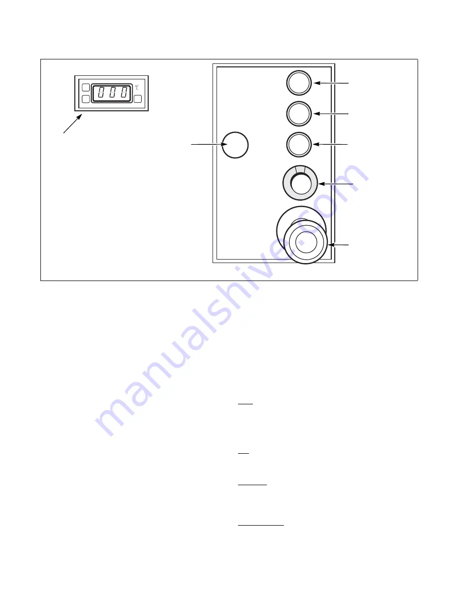
Start

1. Push green "Tension" button: the circulation 

pump starts to work, the burner starts.

2. Set to desired temperature.

IMPORTANT: The working temperature varies 
depending on the fabric being ironed. It must be at 
least 302

o

F (150

o

C) but never to exceed 365

o

(180

o

C).

3. Push the green "Start" button to start machine. 

Green pilot comes on. Bed is pressed against 
roller, exhaust is started, and roll starts to turn. 
For best results, adjust speed.

Stop

1. Push red stop button, bed opens and roll stops at 

once. The machine remains on temperature.

IMPORTANT: When pushing emergency stop 
button, all motors and the burner are cut off and 
bed opens automatically. Restarting is only possible 
by resetting the emergency stop button (turn 
clockwise) and pushing the power/tension button 
again. Touching the finger guard will stop the roll 

at once, but temperature will remain constant. To 
start again, push start button. 

IMPORTANT: When the finger guard is tripped 
the bed remains pressed against the roll. It is 
strongly recommended to start the roll as soon as 
possible or to stop the machine completely.

Temperature Setting

NOTE: Set temperature to read in degrees 
Fahrenheit.

SET:

 Push to display the set point valve. The set point 

can be changed within 3 seconds with the "UP" or 
"DOWN" button. The control will automatically 
switch back to normal operating mode within 3 
seconds; the last entered set point sill stay in memory.

UP:

 Used to increase the set point value, as well as the 

parameter when in programming. Pushing the button 
for several seconds will accelerate the change rate.

DOWN:

 Used to decrease the set point valve, as well 

as the parameter when in programming. Pushing the 
button for several seconds will accelerate the change 
rate.

LED "OUT":

 Status light of the output. Blinks when 

in set point display/change mode or during 
programming.

FWF50N

POWER/TENSION 
ON/OFF 

START BUTTON 
ROLL

EMERGENCY 
STOP

SPEED 
ADJUSTMENT

STOP BUTTON 
ROLL

GAS BURNER 
OFF

TEMPERATURE 
ADJUSTMENTS

Summary of Contents for UL15F069

Page 1: ...ated Finishers 15 inch 370 mm Models and 20 inch 500 mm Models Refer to Page 2 for Model Identification Part No 1800001R1 September 2007 Keep These Instructions for Future Reference If this machine ch...

Page 2: ......

Page 3: ...dels 7 UL20 Models 7 Dimensions 8 Dimensions 9 Pre Installation Inspection 10 Location Requirements 10 Moving Finisher with Crane 11 Moving Finisher with Forklift 11 Electrical Connection 12 Gas Conne...

Page 4: ...1800001 2 Introduction Model Identification Information in this manual is applicable to these models UL15F069 UL20F079 UL15F079 UL20F099 UL15F099 UL20F118 UL15F118 UL20F130 UL15R069 UL20R079 UL15R079...

Page 5: ...ance Refer to Figure 1 for serial plate location Figure 1 Replacement Parts If literature or replacement parts are required contact the source from whom the machine was purchased or contact Alliance L...

Page 6: ...used to inform the reader of specific procedures where minor machine damage will occur if the procedure is not followed NOTE The word NOTE is used to communicate installation operation maintenance or...

Page 7: ...and warnings Learn all aspects of the equipment such as what is hot which parts move all safety shut offs and all emergency procedures Do not come close to moving or heated parts Do not wear loose cl...

Page 8: ...ding to the Installation instructions in this manual All connections for electrical power grounding and gas supply must comply with local codes and be made by licensed personnel when required 22 Do no...

Page 9: ...Approx Shipping Weight 1874 lb 850 kg 2050 lb 930 kg 2491 lb 1130 kg 2976 lb 1350 kg Approx Net Weight 1543 lb 700 kg 1720 lb 780 kg 2161 lb 980 kg 2646 lb 1200 kg UL20 079 UL20 099 UL20 118 UL20 130...

Page 10: ...3 5 in 90 mm A Refer to Table 1 Roll Exhaust 3 in 75 mm 60 in 1529 mm 47 in 1199 mm Electrical Connection B Refer to Table 1 C Refer to Table 1 SIDE VIEW BACK VIEW FRONT VIEW TOP VIEW Dimension UL15 0...

Page 11: ...8 in 1723 mm 47 in 1199 mm Gas Inlet 5 in 12 7 mm Gas Outlet 3 5 in 90 mm Roll Exhaust 3 in 75 mm B Refer to Table 2 C Refer to Table 2 SIDE VIEW BACK VIEW TOP VIEW FRONT VIEW Dimension UL20 079 UL20...

Page 12: ...gly Location Requirements It is strongly recommended that the purchaser be present during installation and the first tests To assure compliance consult and adhere to building local code requirements a...

Page 13: ...ld be moved with a forklift as close as possible to the area where it will be installed Use a forklift of sufficient capacity to lift the packaged unit according to the following procedures IMPORTANT...

Page 14: ...ect to individual branch circuit Before preceding check for proper rotation of exhaust fan hydraulic pump and circulation pump All three should be moving in the direction indicated by the arrow on par...

Page 15: ...100 feet 30 50 m 125 feet 38 13 m 150 feet 45 75 m Based on 0 3 Water Column Pressure Drop for Length Given 100 000 75 in 19 05 mm 75 in 19 05 mm 1 in 25 4 mm 1 in 25 4 mm 1 in 25 4 mm 1 in 25 4 mm 20...

Page 16: ...the pressure indicated on the finisher s serial plate 3 Install a pressure regulator valve obtain locally suited for the nature and flow rate of the gas used in the tube system near the finisher IMPO...

Page 17: ...te outlets IMPORTANT Outlet ducts used for the finisher s exhaust may under no circumstances be shared with other devices Finisher produces combustible lint To reduce the risk of fire the finisher mus...

Page 18: ...first heating of the machine air a moisture must be purged out of the system To do this 1 Take off existing hose Do not throw away Refer to Figure 5 2 Connect the teflon hose provided on top of the ma...

Page 19: ...ssues 3 Check that there are no foreign objects between the roll and the bed 4 Check to ensure the opening between the feed band and finger guard is not more than 6 inch 15 mm and that it is working p...

Page 20: ...ouching the finger guard will stop the roll at once but temperature will remain constant To start again push start button IMPORTANT When the finger guard is tripped the bed remains pressed against the...

Page 21: ...ing Waiting too long to renew the padding can damage the beds Daily 2 to 4 times a day pass a wax cloth through ironer Check condition of padding Dust the machine Every Three Months Clean ventilation...

Page 22: ...Remove all dust Scotch Brite and cloth 9 Restore to original hydraulic pressure 10 Heat the beds and pass a wax cloth to grease the beds NOTE Wax should be applied regularly but sparingly so as not to...

Page 23: ...NOTE Never turn the rollers in cold beds 7 Trim off the felt around circumference of rollers at each end Cut off overlapping felt at each side of the roller 8 Make holes in the felt and screw the felt...

Page 24: ...Remove cap from side of hydraulic pump Refer to Figure 7 2 Using a 4 mm Allen Wrench adjust screw as follows turn clockwise up to increase hydraulic pressure turn counter clockwise down to decrease hy...

Page 25: ...2 Wrap plastic around roller s 3 Grease the beds with some oil to prevent rusting by feeding an oil cloth 4 Keep carrying out the annual maintenance oil change greasing etc 5 Before starting the iron...

Page 26: ...DKL1 out of order 2 Motor out of order 1 Change push button DKL1 2 Check motor print C2 4 The bed closes but the roll does not turn 1 Foot pedal option pushed 2 Finger guard pushed 3 Frequency contro...

Page 27: ...l be ironed b The ribbon length is uneven Uneven length ribbons will not drive the roll evenly Only a few articles can be ironed before the finish quality deteriorates The operators must wait a few mi...

Reviews: