72
801683
Section 5 Service Procedures
© Copyright, Alliance Laundry Systems LLC – DO NOT COPY or TRANSMIT
To reduce the risk of electric shock, fire, explosion, serious injury or death:
• Disconnect electric power to the washer before servicing.
• Never start the washer with any guards/panels removed.
• Whenever ground wires are removed during servicing, these ground wires must be
reconnected to ensure that the washer is properly grounded.
• Motor not grounded! Disconnect electric power before servicing motor.
W485
WARNING
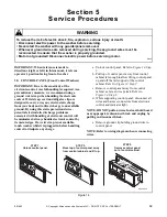
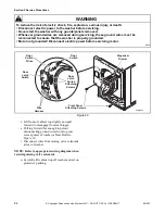
(2) Loosen setscrew holding switch knob to
switch shaft. Refer to
.
(3) Remove knurled nut holding switch to
control panel. Refer to
NOTE: Lockwasher must be between switch and
control panel when installing switch. Refer to
Figure 17.
(4) Disconnect wires from switch.
NOTE: Refer to appropriate wiring diagram when
rewiring switch.
i.
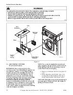
Indicator Lights (Refer to Figure 16.)
(1) Remove two control panel attaching
. Lay assembly
forward on protective pad on cabinet top.
(2) Disconnect wires from light.
NOTE: Refer to wiring diagram when rewiring
light.
(3) Squeeze locking tabs together and pull light
out rear of control panel.
32. CONTROL CABINET – Models with Short
Cabinet
a. Remove screws holding control panel to
control cabinet. Refer to
. Remove
panel.
b. Remove screws holding cabinet top to control
cabinet. Refer to
c. If area or space permits, lift cabinet top to a
vertical position.
NOTE: To avoid damage to hinges, be sure to
support top with a chain (not included) or
equivalent. Refer to Figure 23
d. Remove cabinet top from washer by removing
nuts and carriage bolts holding cabinet top and
hinges to control cabinet. Refer to
e. Carefully lift cabinet top off washer and set out
of the way to prevent damage.
f. Remove screws holding control cabinet base to
control cabinet. Refer to
g. Remove screws holding control shield (with
controls attached) to bottom rear flange of
control cabinet. Refer to
h. Remove screws holding control cabinet to top
flange of side panels. Refer to
.
i. Carefully lift control cabinet assembly off
washer.
j. Remove screws holding left, right and rear
control cabinets together. Refer to
.
Figure 17
W4
9
2
S
E1B
Lockwa
s
her
s
Panel
S
crew
Wa
s
h
Temperature
S
witch
Motor
S
peed
S
witch
S
et
s
crew
Knurled
Nut
Knob
Summary of Contents for HWFB61QN1102
Page 2: ......


