801683
105
Section 5 Service Procedures
© Copyright, Alliance Laundry Systems LLC – DO NOT COPY or TRANSMIT
To reduce the risk of electric shock, fire, explosion, serious injury or death:
• Disconnect electric power to the washer before servicing.
• Never start the washer with any guards/panels removed.
• Whenever ground wires are removed during servicing, these ground wires must be
reconnected to ensure that the washer is properly grounded.
• Motor not grounded! Disconnect electric power before servicing motor.
W485
WARNING
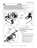
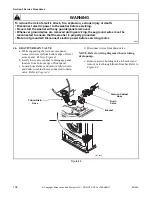
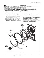
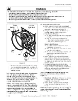
(3) Open loading door. Carefully remove wire
clamp ring from groove with small flat
blade screwdriver. Spring is in the
6 o’clock position. Refer to
.
NOTE: To avoid damage to spring, use screwdriver
on wire clamp ring to right or left of spring.
(4) Grasp loading door seal lip. Refer to
, Step “1”.
NOTE: To avoid damage to door seal, DO NOT use
pliers or sharp objects to grasp the door seal lip. If
lip is damaged, seal will leak.
(5) Using a circular motion, pull seal up
, Step
“2”), and down (
, Step “3”).
(6) When seal releases from lip of front panel,
pull out and remove the seal from front
panel around door opening. Refer to
, Step “4”.
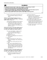
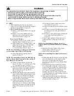
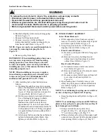
(7) While supporting the front panel assembly,
remove the two bottom front panel corner
screws. Refer to
. Remove front
panel (with loading door attached) away
from washer as far as wire permits.
(8) Unplug wire harness from both the door
latch switch and from the door switch.
Refer to
. Remove clips holding
wire harness and door seal hose along top
flange of front panel and remove front
panel.
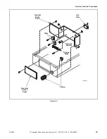
(9) Unlock and remove meter case service
door. Refer to
(10) Remove shoulder screw from inside meter
case.
(11) Remove two screws holding cabinet top to
front flange of side panel. Refer to
.
(12) Remove security bolt (if present) from left
rear corner of cabinet top. Refer to
.
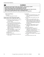
b. If area or space permits, lift cabinet top to a
vertical position by hinging it on the rear
hinges. Refer to
.
NOTE: To avoid damage to hinges, be sure to
support cabinet top with a small chain or something
similar. Refer to Figure 23.
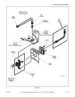
c. Mixing valve is located on upper back right
corner of rear panel. Refer to
d. Shut off external hot and cold water supply and
remove two inlet hoses.
e. Loosen hose clamp and remove mixing valve-
to-dispenser hose at the mixing valve. Refer to
.
f. Remove wire harness disconnect blocks from
mixing valve solenoid terminals. Refer to
.
NOTE: Refer to wiring diagram when rewiring
solenoids.
g. Go to rear of washer and remove screw holding
mixing valve and plate to rear panel, then
remove valve and plate out through opening in
rear panel. Refer to
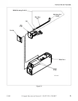
h. Remove screws holding valve to mixing valve
.
Summary of Contents for HWFB61QN1102
Page 2: ......

