background image

© Copyright, Alliance Laundry Systems LLC – DO NOT COPY or TRANSMIT

7

512042

DO NOT use plastic or thin foil ducting. Rigid 
metal duct is recommended.

Locate dryer so exhaust duct is as short as 
possible.

Be certain old ducts are cleaned before installing 
your new dryer.

Use 4 inch (102 mm) diameter rigid or flexible 
metal duct.

The male end of each section of duct must point 
away from the dryer.

Use as few elbows as possible.

Use duct tape or pop-rivets on all duct joints. DO 
NOT use sheet metal screws or fasteners on 
exhaust pipe joints which extend into the duct 
and catch lint.

Ductwork that runs through unheated areas must 
be insulated to help reduce condensation and lint 
build-up on pipe walls.

Each exhaust duct must be vented separately.

Install backdraft dampers (obtain locally) in 
multi-dryer installation.

When exhausting the dryer to the outdoors, the 
dryer can be installed with “0” inch clearance at 
the sides and rear. Clearance of the duct from 
combustible construction must be a minimum of 
2 inches (5.08 cm).

For proper operation, it is important that the dryer 
has an ample amount of outside make-up air. The 
free area of any opening for the introduction of 
outside air must be at least 25 in

2

 (163 cm

2

).

In mobile home installations, dryer exhaust duct 
must be secured to mobile home structure.

Dryer exhaust duct MUST NOT terminate under 
mobile home.

Exhaust duct must not be connected to any other 
duct, vent, or chimney.

Never install flexible duct in concealed spaces, 
such as a wall or ceiling.

Dryer exhausts 220 cfm (measured at back of 
dryer).

Static pressure in exhaust duct should not be 
greater than .6 inches water column (1.5 cm), 
measured with manometer placed on exhaust 
duct two feet (61 cm) from dryer (check with 
dryer running and no load).

Exhausting dryer in hard-to-reach locations can 
be done by installing 521P3 Flexible Metal Vent 
Kit (available as optional equipment at extra 
cost).

Failure to exhaust dryer properly will void 
warranty.

NOTE: Venting materials are not supplied with the 
dryer (obtain locally).
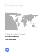
DRY2010N

1

Two (2) individual, separately vented, 
4 in. (10 cm) exhaust ducts.

Figure 4 

DRY2010N

DON’T

DO

1

Summary of Contents for 512042R4

Page 1: ...machine www comlaundry com Installation Instructions for Stacked Dryers Dimensions 3 Before You Start 4 Installing the Dryer 5 Installer Checklist Back Cover Date Purchased _____________________ Mode...

Page 2: ...pplier s instructions If you cannot reach your gas supplier call the fire department Installation and service must be performed by a qualified installer service agency or the gas supplier W052 FOR YOU...

Page 3: ...n 13 3 cm 8 0 in 20 3 cm 44 1 in 112 cm 75 38 in 191 5 cm 15 4 in 39 1 cm 37 44 in 95 1 cm 15 44 in 39 2 cm DRY2285N With leveling legs turned into base 1 3 8 in N P T Gas Connection DRY2285N GAS DRYE...

Page 4: ...re You Start Supplies For most installations the basic supplies you will need are Figure 1 D818I 1 Wrench 2 Screwdrivers 3 Level 4 Teflon Tape 5 Duct Tape 1 2 3 4 5 Any disassembly requiring the use o...

Page 5: ...side the dryer with a 1 4 in driver All four legs must rest firmly on the floor so the weight of the dryer is evenly distributed The dryer must not rock The dryers needs sufficient clearance and an ad...

Page 6: ...f fire and combustion gas accumulation the dryer MUST be exhausted to the outdoors W116 To reduce the risk of fire and the accumulation of combustion gases DO NOT exhaust dryer air into a window well...

Page 7: ...tible construction must be a minimum of 2 inches 5 08 cm For proper operation it is important that the dryer has an ample amount of outside make up air The free area of any opening for the introductio...

Page 8: ...not in operation outer end of exhaust pipe must have a weather hood with hinged dampers obtain locally NOTE Weather hood should be installed at least 12 inches 30 5 cm above the ground Larger clearan...

Page 9: ...dryer Make sure you do not damage the pipe threads when removing the cap 3 Connect to gas supply pipe using a new flexible stainless steel connector To reduce the risk of gas leaks fire or explosion...

Page 10: ...0 Btu ft3 93 1 MJ m3 service must be supplied at 10 1 5 inch water column pressure For proper operation at altitudes above 3000 feet 915 m the L P gas valve spud orifice size must be reduced to ensure...

Page 11: ...ical service for the dryer should be of maximum rated voltage 208 or 240 Volt depending on heating element listed on the nameplate Do not connect dryer to 110 115 or 120 Volt circuit Heating elements...

Page 12: ...r Circuit Breaker 6 Neutral 3 Neutral Wire 7 Terminal Block in Dryer NOTE The power cord is NOT supplied with the electric dryer Type of power cord and gauge of wire must conform to local codes and in...

Page 13: ...ord into an outlet Use an acceptable indicating device connected to the center grounding pin of the plug and the green screw on the back of the cabinet 8 Reinstall access cover and screw Connecting Po...

Page 14: ...terminal block as follows a Red wire to L1 terminal b Black wire to L2 terminal c White wire to Neutral terminal Figure 15 NOTE When installing the white wire loop the free eyelet end of the ground wi...

Page 15: ...en pull down removing door liner from door panel 4 Rotate door panel 180 degrees as shown 5 Remove door strike from door liner and reinstall on opposite side 6 Insert liner under flange on bottom of d...

Page 16: ...plate for specific electrical requirements NOTE The wiring diagram is located behind the control panel inside the control cabinet When plugging in the dryer Do not overload circuits Do not use an ada...

Page 17: ...meet the above specifications and or if you are not sure the laundry room has an effective ground have a qualified electrician or your local electrical company check it and correct any problems NOTE...

Page 18: ...ter the dryer has operated for approximately five minutes observe burner flame through lower front panel Adjust the air shutter to obtain a soft uniform blue flame A lazy yellow tipped flame indicates...

Page 19: ......

Page 20: ...Connect Dryer Exhaust System CHECK DRY2010N 3 GAS ONLY D258I CHECK Connect Gas Supply Pipe Check for Gas Leaks 4 D699I W315IE0A ELECTRIC ONLY Connect Electrical Cord CHECK Reverse Door if Desired 5 DR...

Reviews: